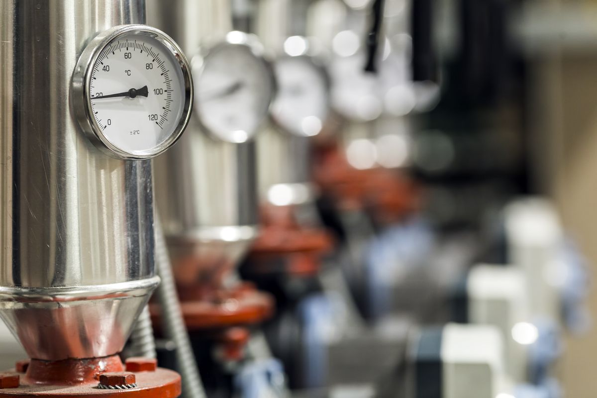
Magister Hydraulics has received EU grant support for a new investment focused on reducing
energy intensity, improving production efficiency, and strengthening the long-term
competitiveness of the company.
Project Number
BG16RFPR001-2.004-1370-C01
Duration
03/2026 – 03/2027
Total Budget
€28,305.12
EU Funding
€18,398.33
Magister Hydraulics is pleased to announce that the company has received grant funding from
the European Union for the implementation of a project aimed at improving energy efficiency
in its operations.
The project focuses on the installation of energy-efficient compressed air compressors,
together with compressed air tanks, as part of a broader effort to modernize the production
environment at Magister Hydraulics. This investment will support more efficient use of
energy, better optimization of production processes, and a reduction in the overall energy
intensity of the company.
By improving the performance of key production infrastructure, Magister Hydraulics expects
to strengthen operational reliability and create better conditions for sustainable growth.
The investment also contributes to the company’s long-term objective of increasing
competitiveness while applying more responsible and resource-efficient industrial practices.
The project is an important step in Magister Hydraulics’ continued commitment to modern,
efficient, and sustainable manufacturing.
We believe that investments in energy efficiency are directly linked to better productivity,
improved stability in operations, and stronger long-term value for our customers and
partners. Magister Hydraulics will continue to invest in practical improvements that support
both business performance and environmental responsibility.
Project Certificates
Certificate in English
Official project certificate for “Improving the energy efficiency of Magister
Hydraulics”.
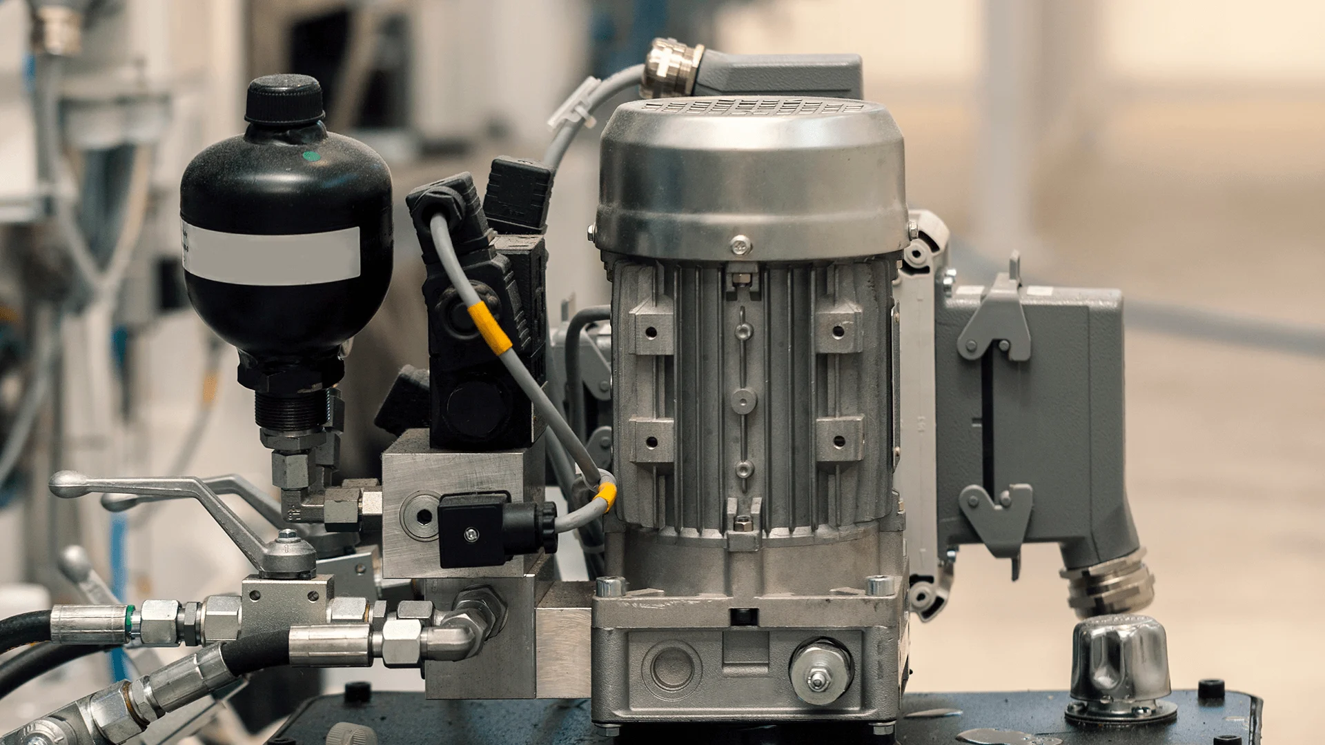
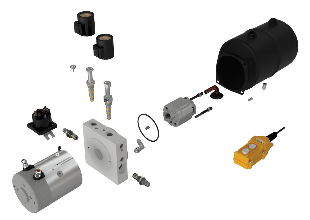
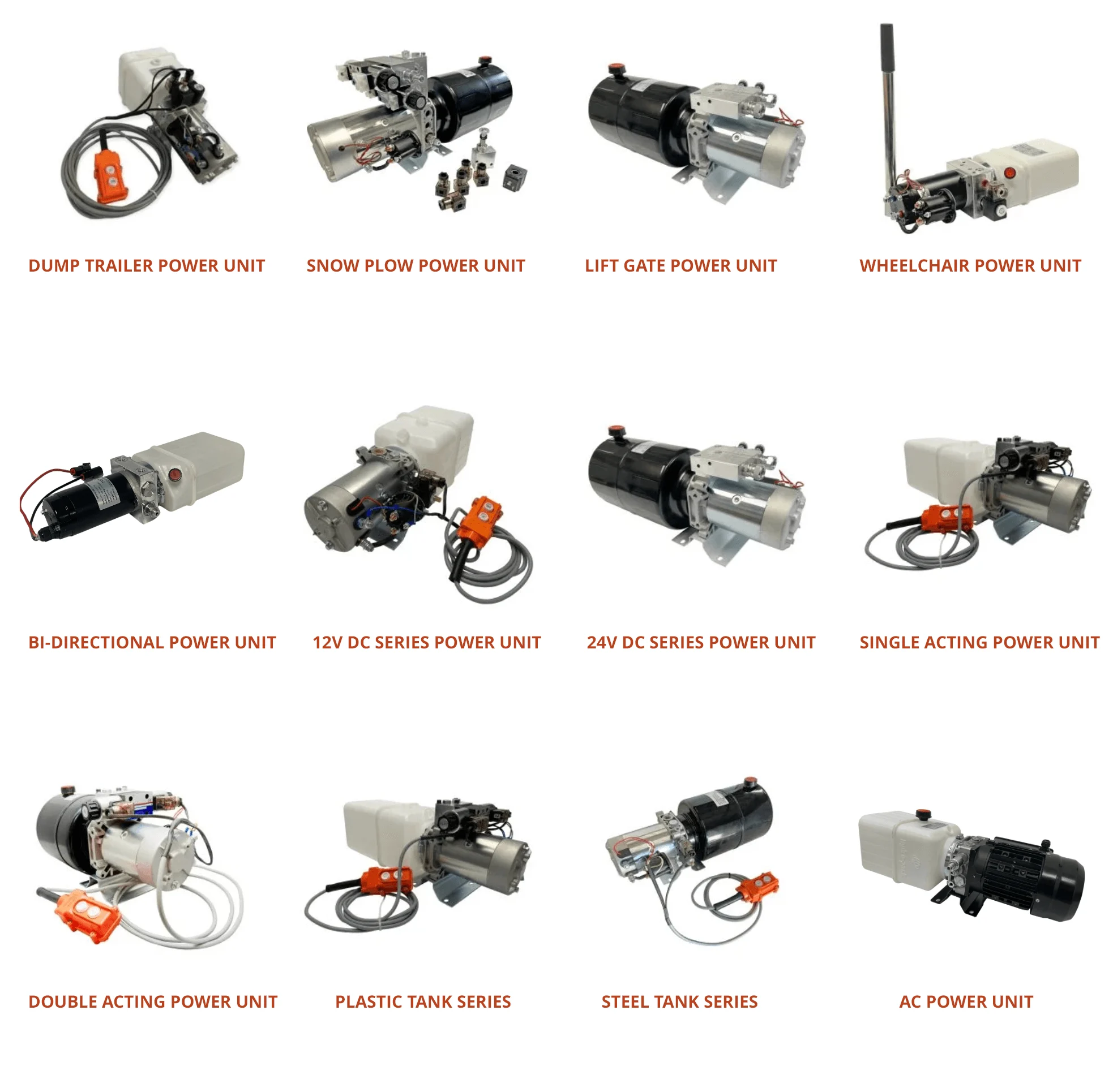
A Hydraulic Power Unit (HPU)—also called a hydraulic power pack—is a self-contained system that generates, regulates, and transmits hydraulic pressure to drive machinery. It combines a motor, pump, and reservoir to pressurize hydraulic fluid and deliver controlled power to cylinders, motors, and actuators across industrial, mobile, and marine applications.
How a Hydraulic Power Unit Works
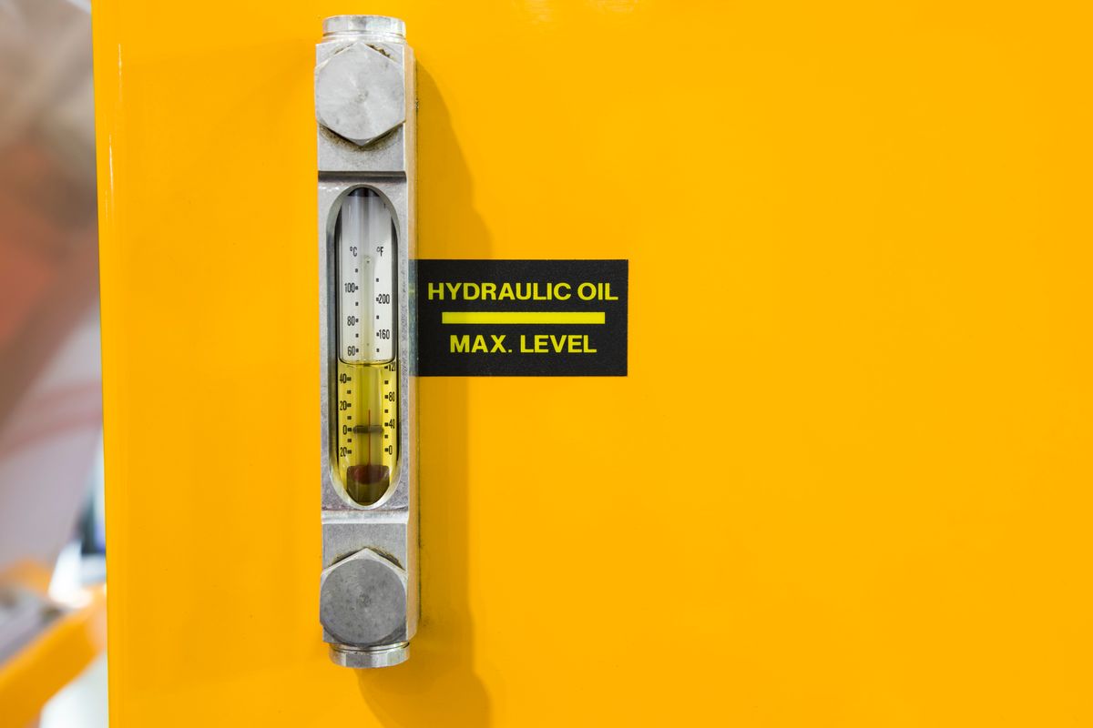
An HPU converts mechanical energy (from an electric motor or combustion engine) into hydraulic energy by pressurizing fluid. The pressurized fluid travels through hoses and valves to actuators, where it’s converted back into force or motion. A basic cycle looks like this:
Fluid Intake: Pump draws fluid from the reservoir.
Pressurization: Pump forces fluid into the circuit under high pressure.
Flow Control: Valves direct and regulate flow to actuators.
Return: Fluid returns to reservoir, dissipating heat and releasing entrained air.
Compared with simple pumps, HPUs often add multi-stage pressurization, filtration, and temperature control for demanding duty cycles.
Panels or PLCs provide start/stop, pressure/temperature monitoring, fault alarms, and diagnostics.
Energy Conversion & Efficiency
Mechanical → Hydraulic → Mechanical: the motor delivers torque to the pump; the pump pressurizes fluid; actuators convert pressure/flow into linear or rotary motion. Overall efficiency depends on pump design, component quality, fluid condition, and thermal management.
Selecting the Right HPU
Pressure rating (PSI) and flow rate (GPM)
Reservoir volume (often 3–5× pump flow per minute)
Motor power (HP) — based on pressure × flow / 1714 ÷ efficiency
Size/weight and mounting constraints
Power source: electric vs. diesel/gas for the site conditions
Inspect hoses, seals, and fittings; fix leaks promptly.
Track operating temperature and pressure; clean coolers.
Keep reservoirs and breathers clean to reduce contamination.
Common Issues & Fixes
Problem
Cause
Solution
Contaminated fluid
Dirty oil or clogged filters
Replace fluid & filters; check breathers
Overheating
Insufficient cooling or low fluid
Service cooler; restore fluid level; verify viscosity
Low pressure
Pump wear or internal leakage
Inspect pump, seals, and relief settings
Noise/vibration
Air entrainment or misalignment
Bleed system; realign couplings; check mounts
Conclusion
A well-designed hydraulic power unit is the heart of a hydraulic system—converting energy into precise, controllable motion. With proper sizing, smart controls, and proactive maintenance, HPUs deliver outstanding power density, efficiency, and reliability across industrial, mobile, aerospace, marine, and agricultural applications.
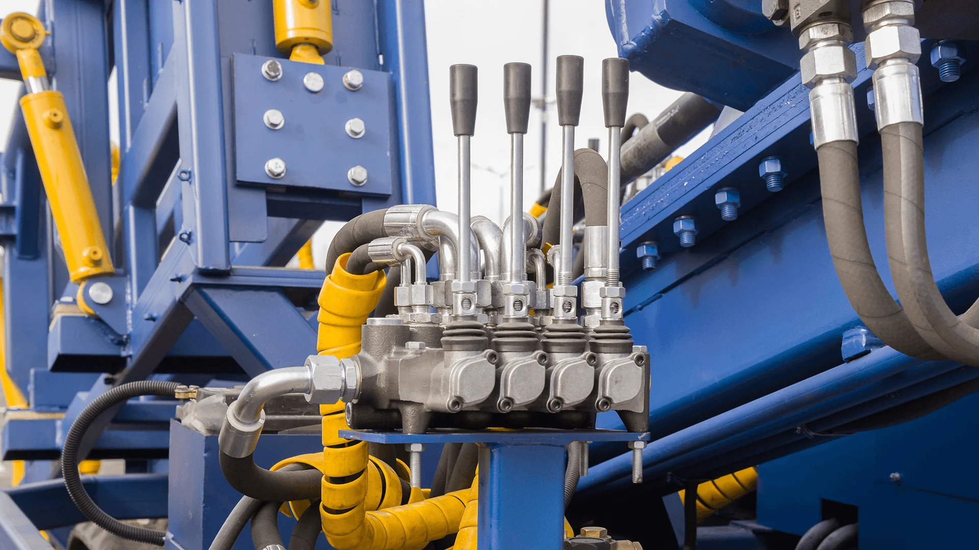
Hydraulic valves are critical components in fluid-power systems, used to control the flow, pressure, and direction of hydraulic fluid. Found everywhere from industrial presses to farm equipment and construction machinery, these valves translate operator input into smooth, controlled mechanical motion.Built to withstand high pressures—often over 3,000 psi (≈ 20 MPa)—hydraulic valves must be durable and precisely engineered. They are typically made from steel, cast iron, or other high-strength alloys that can handle continuous heavy-duty use.
How Hydraulic Valves Work
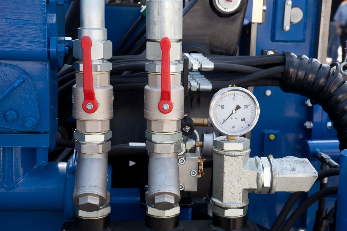
A hydraulic system operates by using pressurized fluid (usually oil) to transmit force. The pump generates pressure, sending the fluid through hoses and pipes to cylinders, motors, or actuators. Hydraulic valves are the control points in this circuit. By opening, closing, or partially restricting flow, they determine:
When fluid moves,
Where it goes, and
At what pressure or speed it acts.
This precise regulation allows for smooth lifting, pushing, or rotating motions—essential for everything from excavators to injection-molding machines.
Main Types of Hydraulic Valves
Hydraulic valves fall into three main categories, each serving a distinct function.
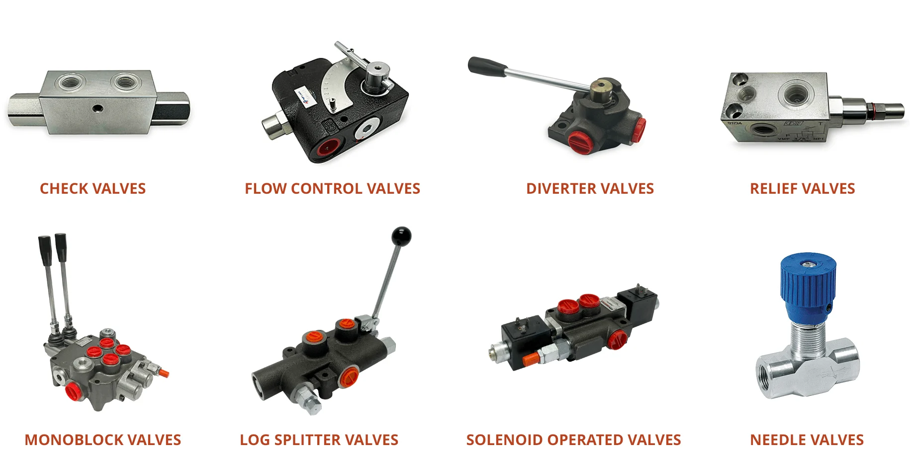
These valves route the fluid to different parts of the system. The simplest is a check valve, which allows flow in one direction only. More complex valves—like 4/3 directional control valves—have multiple ports and positions:
Valve Position
Function
Neutral
All ports closed or recirculating to tank.
Extend
Fluid directed to extend the cylinder.
Retract
Fluid directed to retract the cylinder.
Directional control valves may be on/off (binary) or proportional, allowing partial flow for smoother speed control. Servo valves are high-precision versions used in robotics and aerospace applications.
Electric current moves a plunger to shift the valve. Used for automation and remote control.
Hydraulic / Pneumatic Pilot
A small control valve uses pressurized fluid or air to actuate a larger main valve—ideal for high-pressure or hazardous environments.
Key Components of a Hydraulic Valve
Valve Body – main housing containing internal ports.
Spool or Poppet – moves within the body to open or close flow paths.
Actuator Shaft – transmits control force to the spool.
Feedback Spindle – provides position feedback for accurate control.
Seals and Rings – prevent internal leakage.
Pilot Motor – operates the main valve under high pressure (if applicable).
Specifications to Consider
When selecting a hydraulic valve, engineers evaluate:
Valve Type & Configuration: number of ports and positions (e.g., 4/3 valve).
Operating Pressure Range: minimum and maximum working pressure.
Flow Rate or Cv: the capacity to pass fluid (GPM / LPM).
Port Size & Style: threaded, flanged, or manifold connections.
Media Compatibility: type of hydraulic fluid—mineral oil, glycol, or bio-oil.
Temperature Range: safe operating temperature limits.
Actuation Voltage: for solenoid valves, specifies AC/DC control voltage.
Mounting Type: line-mounted or sub-plate/manifold installation.
Application: industry use—mobile hydraulics, manufacturing, aerospace, etc.
Materials and Construction
To endure constant high-pressure operation:
Valve bodies are usually steel or cast iron.
Internal moving parts use hardened and ground spools for wear resistance.
Sealing materials are chosen based on the working fluid and temperature range.
Conclusion
Hydraulic valves are the control center of every hydraulic system—balancing precision, safety, and durability. From basic manual check valves to sophisticated electro-hydraulic servo valves, they make it possible to convert pressurized fluid energy into smooth, controllable mechanical motion.
Understanding their types, construction, and operation ensures safer, more efficient, and longer-lasting hydraulic machinery.
Hydraulics use pressurized fluid to transmit energy, multiply force, and deliver precise, controlled motion. From car brakes and construction cranes to manufacturing presses and aircraft systems, hydraulic technology enables smooth, reliable, high-force operation across countless applications.
A Brief History
While water power has been used for centuries, modern hydraulics rests on Pascal’s Law (17th century). In 1795, Joseph Bramah applied this principle to invent the hydraulic press, launching industrial fluid power.
The Science: Pascal’s Law
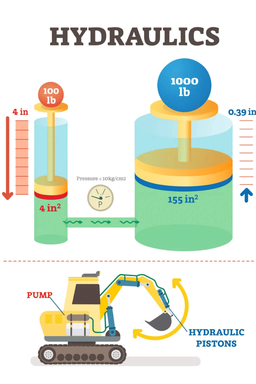
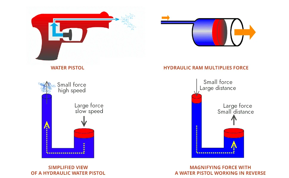
When pressure is applied to a confined fluid, it is transmitted equally and undiminished in all directions.
Because hydraulic fluids are nearly incompressible, a small input can produce a much larger output on a bigger piston. Mathematically:
P = F / A (pressure = force / area)
If the output piston has 10× the area of the input piston, it delivers ~10× the force at the same pressure (trading speed for force to conserve energy).
How a Hydraulic System Works
Pressure generation: A pump draws fluid from the reservoir and pressurizes it.
Flow control: Valves direct, regulate, and relieve pressure and flow.
Power transmission: Pressurized fluid moves through hoses and lines in a closed loop.
Work output: Cylinders and motors convert fluid power to linear or rotary motion.
Return & conditioning: Fluid returns to the reservoir for cooling, deaeration, and filtration.
Key Components
Component
Function
Reservoir
Stores fluid; enables heat dissipation and air separation.
Pump
Converts mechanical energy into hydraulic energy (pressure/flow).
Prime mover
Electric motor or engine driving the pump.
Valves
Control direction, flow rate, and pressure (directional, flow, pressure control).
Actuators
Cylinders (linear) and motors (rotary) that do the work.
Hoses & fittings
Carry pressurized fluid between components.
Filters
Remove contaminants to protect components.
Coolers/Heaters
Manage temperature and fluid viscosity.
Hydraulic Circuits
A hydraulic circuit parallels an electric one: the reservoir/pump pair acts as the power source, hoses are the conductors, and actuators are the loads. All parts must form a closed loop so fluid returns to the tank for reconditioning.
Hydraulics in Heavy Equipment
Excavators, loaders, forklifts, cranes, and agricultural machines rely on hydraulics for high torque and precise motion in rugged environments. Operators manipulate small controls while hydraulics deliver large, smooth forces for lifting, digging, steering, and positioning.
Advantages
High power density: Big force from compact components.
Smooth, precise control: Fine speed/position control of actuators.
Self-lubricating: Fluid reduces wear and heat.
Flexible routing: Power transmitted through hoses over distance.
Force multiplication: Small input → large output (with lower speed).
Limitations
Maintenance: Fluids, seals, filters, and hoses need routine service.
Temperature sensitivity: Fluid properties vary with heat.
Leak risk: Requires proper fittings and cleanliness.
Energy losses: Friction and heat reduce overall efficiency.
Maintenance Tips
Inspect routinely for leaks; replace worn hoses and seals.
Keep fluid clean; change and filter on schedule.
Monitor pressure and temperature; verify relief settings.
Service filters, coolers, and breathers regularly.
The Future: Electro-Hydraulics & AI
Modern systems integrate sensors, PLCs, and smart controls for efficiency and safety. Expect broader use of variable pumps, real-time diagnostics, and predictive maintenance — plus AI-assisted optimization for smoother, safer operation.
Conclusion
Hydraulics turn pressurized fluid into prec
In this supporting document, a troubleshooting guide is provided with charts. Every chart is related to a malfunction in the system.
There are many agricultural tools and machines that employ hydraulics for smooth work. And note that a tractor is among these powerful and sturdy machines that rely on the sheer power of hydraulics.
Many people are familiar with hydraulics and hydraulic systems; however, how many among us really know and comprehend how hydraulics work and operate in the tractor loader? Keep in mind that the components and parts of a typical hydraulic system comprise a reservoir, many valves, and a pump. And it’s worth noting that hydraulic control valves and other parts can operate in a system that accurately directs or controls liquid flow.
Hydraulic control valves for tractor loaders are an irreplaceable part that’s used in various kinds of machines in several industries. For example, it is the basis of activity in agriculture and construction. It is hard to imagine modern excavators, tractors, and loaders without a hydraulic control valve.
Hydraulic Valve Defined
We can say that a hydraulic valve is an effective mechanical device that regulates the fluid flow within a specific hydraulic system or circuit. Did you know that you can also use it to completely close a line, redirect pressurized fluid, or even control the degree of flow to specific areas?
Hydraulic valves are usually used in hydraulic power packs in order to direct the fluid either from or to a hydraulic cylinder. Hydraulic valves are important as they help control and regulate the amounts and directions of fluid power in a circuit by closely controlling and tracking the flow rate and pressure in various components of the circuit.
Keep in mind that hydraulic valves in a tractor must be capable of withstanding a high degree of fluid pressure. And it’s because the nature of many contemporary hydraulic systems means high pressure values of 3,000 PSI or even more.
Remember that the hydraulic system in the machine has to lift the bale, the load of dirt and the bale fork. So, even a small tractor’s hydraulic system is usually under massive pressure.
As a result, they are usually constructed of iron or steel. The material should have sufficient strength to withstand continuous and extreme operation under pressurized conditions. Also, the hydraulic reservoir is typically used for storing non-pressurized hydraulic fluid.
How a Hydraulic System Works on a Tractor?
Before learning how to add a hydraulic valve to your tractor, you must know and appreciate how a hydraulic system typically works on any tractor. Note that the hydraulic system works with the help of pumps. These pumps are essential and transfer the fluid from the hydraulic system’s big reservoir to the tractor’s hydraulic system.
And this process raises the level of energy. This is done by gradually raising the pressure. And the motor inside your tractor is the primary power source for pumps. The fluid, or liquid, is under intense pressure and acts on both the piston and rod inside your cylinder.
You should know that each cylinder stroke is important as it converts the fluid power, also called pressure, into valuable mechanical force. The oil level in the reservoir will gradually fall while other parts, such as the piston and rods, extend.
On the other hand, when these parts gradually retract and move back, you will see that all the fluid will slowly get back to the reservoir. After that, you will notice the metallic walls of this reservoir start to trigger a drop in the fluid temperature by letting all the heat energy escape. This is crucial, as it reduces the total pressure in the reservoir. The operation or mechanics of a tractor’s hydraulic system work mainly based on Pascal’s law.
Adding a Remote Hydraulic System
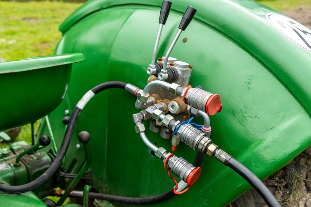
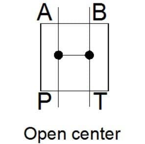
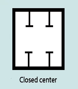
If you attach a remote hydraulic system in order to make your tractor more efficient, it will give you the opportunity to add many hydraulic accessories. A few of them are a log splitter, hydraulic top link, blades, and hydraulic auger motor. Note that if you use an open-centered valve, then the oil will be moving along the standard route to the 3 point until someone pulls the handle on the valve.
After that, the valve may divert the oil to increase or lower your hydraulic accessory. You can reverse the oil or fluid flow to your accessory by pushing the handle in the other direction.
Hydraulic Control Valves and other Crucial Accessories for Tractors
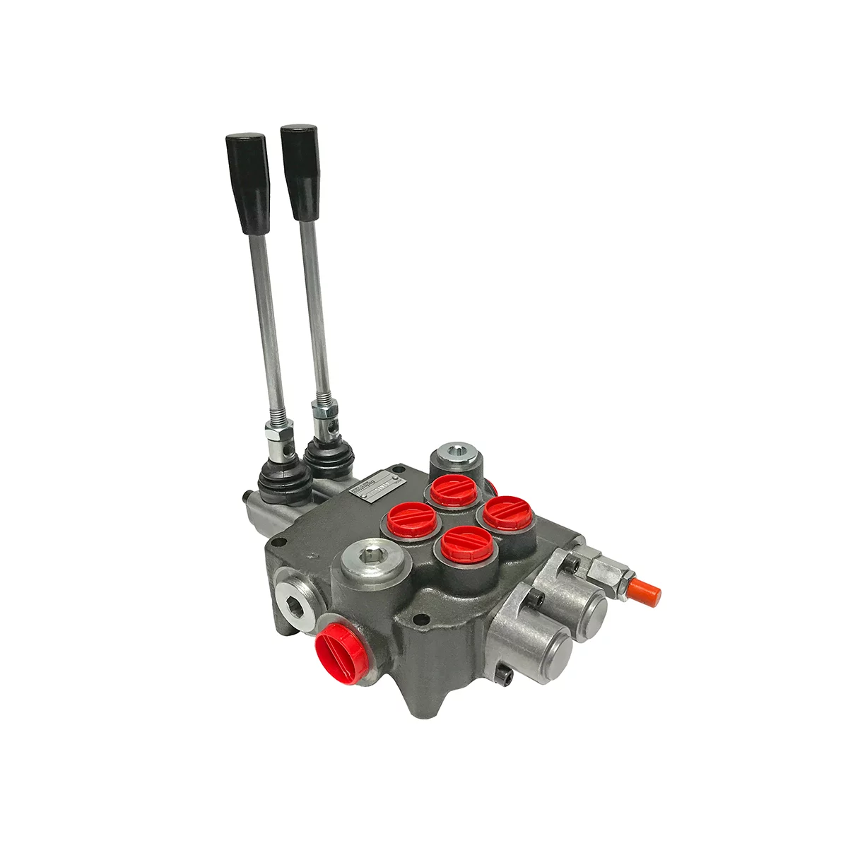
There is no doubt that a hydraulic valve in your tractor loader is among the most integral components of this valuable hydraulic machinery. The valve is crucial. This is because it allows fluid to flow in different directions from either one or multiple sources. It’s worth noting that hydraulic valves in tractor loaders usually have a spool. We can say that the spool is encased in a cylinder that you can control either mechanically or even electrically.
Also, the movement and direction of this spool are integral to restricting fluid flow in the overall system. While it’s quite similar to any directional control valve, this particular type of valve is now extensively used in the industry for loaders.
How to Add Hydraulic Valves to a Tractor
The best thing is that it is simple to turn an old tractor, such as your garden tractor, into a capable earth-moving machine or convert its conventional manual lift system to hydraulic. Did you know that adding hydraulics can multiply a tractor’s engine power manifold?
With the help of hydraulics, you may equip a tractor with a backhoe, a front-end loader, a 3-pt. hitch, and even a dump trailer.
⦁ You should carefully and gradually depressurize the sensitive hydraulic system. It is essential that you consult and go through your specific system documentation to make this step simple.
⦁ Now remove any electrical power or energy source from your system if electric pumps are pressurizing it. You can do this by disconnecting your pump’s power connector or simply pulling its circuit breaker. However, keep in mind that some mechanically driven pumps, like engine-driven pumps, might not have electrical connectors.
⦁ You should remove your old or current valve by removing the current electrical connector. Now place a few buckets underneath the hydraulic valve in a careful manner, and then unscrew the bolts and nuts that are leading to the valve.
⦁ Carefully position your valuable hydraulic valve where it will be installed. You should plug in the fittings present on it and then cap all the ends of either the tubing system or the pipes it will connect to. You should plug all hydraulic lines. These lines may lead to or from the valve. Plugging them will minimize the risk of fluid loss. It is best to use a plastic or aluminum plug that easily screws into the fitting.
⦁ After that, ensure that your valve has a proper and adequate orientation. To ensure that, you may have to use a hydraulic schematic.
⦁ Unplug all the lines that are leading to the valve, and then it is time to connect them carefully to the brand new system valve and tighten the nuts.
⦁ You should supply proper electrical energy if it’s required to provide pressure and force to the hydraulic system. Keep checking for leaks in the system while it is under pressure. You have to understand and appreciate that liquids are incompressible, and they transmit pressure with equal force in nearly all directions.
Things to Consider
Did you know that engines in tractors, even garden tractors, have sufficient power to push hydraulic oil up to 2,000 PSI or even more? The hydraulic system you will find on all major N-Series tractors was carefully designed for plowing.
You can operate a typical control valve on your tractor loader through many methods: manually, electrically, hydraulically, and pneumatically.
You may know that manual valves now tend to work with simpler and easier paddles or levers. These are popular in cases where an operator tends to apply force in order to run the valve. Sometimes, they leverage spring force in order to recover the unique position of this valve.
Conversely, electric hydraulic valves for tractor loaders use electromechanical solenoids for carefully sliding the spool. As the uncomplicated application of electric energy offers much-needed control, these valves are now popular.
However, remember that electric solenoids can’t generate huge or massive forces unless you supply them with considerable amounts of electricity. Did you know that heat generation tends to pose a notable threat and risk to extended and long-term use of the valves? So, many now have a rather limited cycle.
New Tractors and Using Live Hydraulics
Many N-Series tractors, such as the 9N and 2N from Ford-Ferguson, now use a 2-stage clutch. Some even use an efficient hydraulic pump driven directly off an engine. Keep in mind that adding these clutches to these newer models may seem almost impossible; however, few can deny that engine-driven pumps are too complex.
It is worth noting that the original and renowned belly pump comes with a test port. This port offers a convenient and feasible place for supplying pressure and force to any hydraulic system.
Tips for Safe Installation and Operation
When working with a hydraulic system, including hydraulic valves, pumps, and hydraulic hoses and cylinders, it is vital to remember all the proper safety precautions in order to avoid accidents and injuries. Follow these simple rules for safe and simple hydraulic installation as well as operation.
⦁ Always make sure to lower the relevant hydraulic working units, such as valves and any hoses, to the floor.
⦁ You should always park the tractors where kids can’t access them.
⦁ It is in your interest to block all the work units when you need to work on your system.
⦁ Don’t service or repair your hydraulic system if the machine’s engine is on.
When you are transporting your tractor or other machine, it is imperative to lock the cylinder stops in order to hold or secure the working units firmly in place.
⦁ Relieve all of the pressure in the system before you disconnect any oil lines, and after that, discharge the accumulator.
⦁ You have to stay safe by making sure that all of the relevant line connections are tightly secured and none of the lines are damaged. Note that escaping oils and other combustible liquids are serious fire hazards.
⦁ Many pumps and other hydraulic devices, such as control valves, are bulky. So, before removing them, you need to find a reliable support structure, like a chain hoist.
Final Thoughts
For the farming and agriculture industries, a tractor is important for performing various agriculture tasks safely and precisely. And like other heavy vehicles and machinery, tractors use hydraulics for their steering and braking systems. And the hydraulic systems for tractors can be used to lower or raise heavy agricultural implements attached.
The control valve in a tractor has three basic functions. It changes the lifting direction, lifting force, and lifting speed.
Are you looking for the best option for a hydraulic control valve? If so, you must contact the leader in all hydraulic manufacturing, Magister Hydraulics.
All hydraulic control valves and hydraulic gear pumps for tractor loaders are made with high-quality materials designed to prevent corrosion and enhance the function of this key element in the most severe working conditions. In our store, you will find hydraulic control valves, hydraulic hoses, and hydraulic cylinders for tractor loaders of the highest quality. As a result, you can be certain that you are purchasing a proven product that will always work in your business.
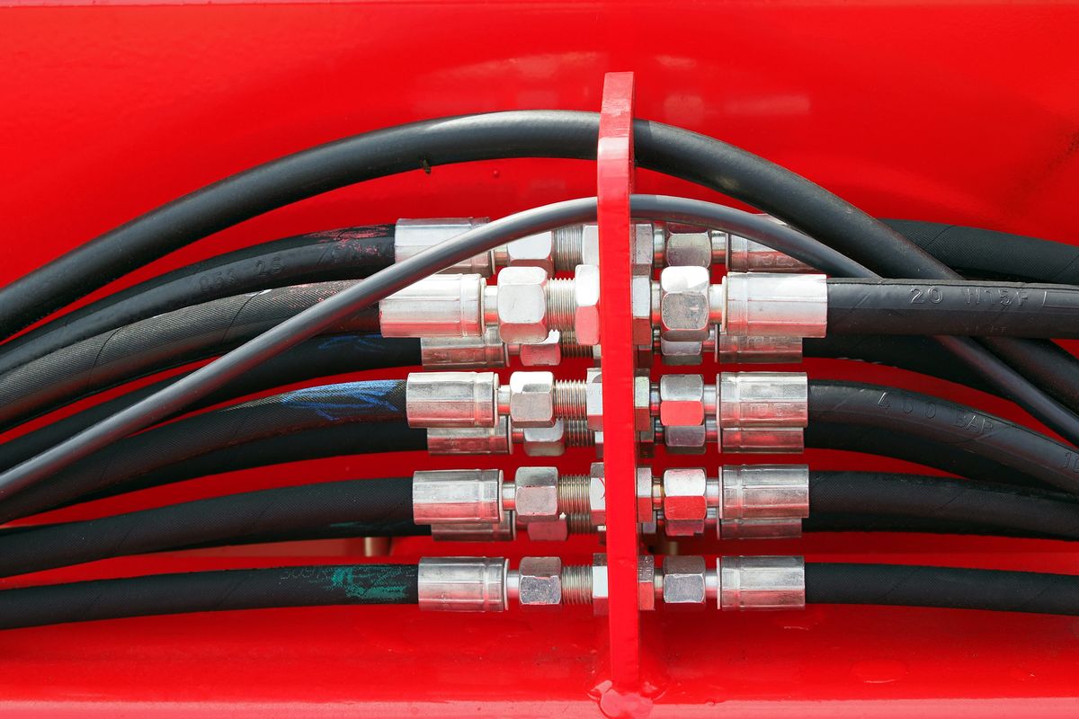
Hydraulic hoses and various couplings are the crucial components of most construction machines and agricultural parts and equipment. You know that couplings and hoses are integral to all hydraulic systems. Wondering why? They transfer fluids from the pump to various machine components, like valves, actuators, etc. And these components change the fluid flow and force. This creates the mechanical force that performs work.
However, like other parts, hydraulic hoses can stop functioning. This malfunction can derail production schedules instantly, costing you considerable time as well as money.
Hose assemblies that suddenly fail or break down are likely to cause injuries, costly cleanup, and property damage? Higher material cost and labor cost are some other issues you may have to deal with.
Depending on your hose, after four to five years of use, the rubber starts to deteriorate. As a result, you may notice visual cracking. Note that if you have a lower-quality hose, it may be sooner than that.
Because of these consequences, many fluid power experts advice replacing hose assemblies before they malfunction.
Hydraulic Hose – Basic Information
Hydraulic hoses move fluid via an effective hydraulic system. Typically, it’s done at higher pressures and speeds. These hoses help operate and function your hydraulic system, whether the system is a modern electric unit on airport runways or excavation equipment at your construction site.
Since they operate at higher pressure, many hydraulic hoses come reinforced and constructed with multiple layers and remain flexible.
A Word on Failure
Several causes and reasons are behind hose failure. And about 80 percent of hydraulic hose malfunctions and failures are because of external damage. Usually, you don’t have to replace your hose unless you find evidence of abrasions and leakage. And a quick visual inspection will help identify one or more reasons for machine hose failures.
There isn’t any reliable or accurate way to confirm just how long your hose assembly may last once you notice these symptoms. So, we recommend that you inspect your hoses, cylinders, and hydraulic valves, frequently. And maintain a comprehensive log of any trouble spots you may find.
Signs and Symptoms Indicating a Need for Replacement of a Hydraulic Hose
The most frequent cause of abrasion is when hose assemblies rub each other or nearby surface? Note that the simplest way to avert hose failure is inspecting them. You should look for many different issues during the inspection.
A couple of signs may indicate that your hose may no longer work. For instance, you may have to replace the hose in these cases:
⦁ Distortion in or crushed hose assemblies ⦁ Worn out marks on a hose that may impair its structural integrity ⦁ Considerable surface damage (in addition to small nicks, marks, and scuffs) ⦁ Exposure of wire within your hose ⦁ Fluid leakage ⦁ Kinks (indicates incorrect routing) ⦁ Twisted hoses (indicates poor routing) ⦁ Corroded fittings
Flexing your hose aggressively and twisting it can lower hose life. Look out for these signs that the hose on your commercial equipment or agriculture machinery needs replacement. You will be happy to know that habitual inspections can show these problems and issues.
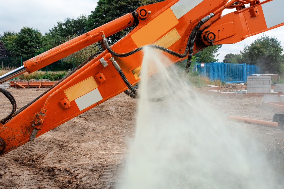
An incident in construction as a hydraulic hose on excavator split and liquid started sprinkling around under high pressure
Steps to Replace a Hydraulic Hose Assembly
While you can get professional help and have somebody replace your hose, usually the job is more dirty than complex or difficult. This means you can probably do it. So, if you have no problem rolling up those sleeves and perform the job yourself, you can save some time and valuable money.
Whenever your hose assembly exhibits the signs or conditions above, it is better to change it. You can use these steps to change your worn or failing hose.
⦁ Safety first! Use gloves and other safety tool, such as a pair of goggles and keep yourself safe from dangerous fluid. Hydraulic liquids and fluids could be toxic. It will likely hurt any part of your body that it contacts. So, it is better to secure yourself with safety equipment.
⦁ You should determine the issue with the part. If it is leaking, you must know which hose is effected. Also, know its location before starting. Use cardboard, or some papers, to follow the oil leak. You must perform checking on the broken hose before completely removing it.
⦁ Staying safe is important; so, releasing all pressure timely from the system is essential. Refrain from operating any hydraulic equipment if there’s pressure inside the system as these liquids may spray out and end up hurting you, and you don’t want that.
⦁ Now determine which system parts must be changed in order to get rid of the problematic hose. Considering the situation carefully is crucial to making sure that repairing the part fixes the problem.
⦁ Prep the system and notice any parts connected to your hose assembly. This will ensure that they do not delay the replacement. For example, you should lower components so they don’t fall and you get a clear view.
⦁ Also, get the best tools. For example, use a saw designed exclusively for hoses when changing parts.
⦁ Undo the fittings connecting the hose assembly to your machine. The important part is to release the part that attaches the hose to your main equipment. It’s often the valve spool, the cylinder, or even coupling. Looking to replace multiple hoses? If so, color coding or marking the ends of each is a good idea to maintain proper connections.
⦁ When these fittings are loose, carefully remove your assembly. Now, pour some residual fluid into your waste bin or container.
⦁ Before installing the new part, seal everything with a lint-free rag.
⦁ Use original parts from the OEM to get the best results. This helps ensure that your hoses fit and last a long time. Get the proper hose by simply matching your new part with the former. The thickness and width should be same. Using low-quality parts can significantly damage your machine.
⦁ Clean your new hose and this existing assembly and get rid of debris. All dirt or oil on exterior parts must be cleaned. If your hose is likely to rub against your machine, buy a good abrasion sleeve and minimize the risk of severe damage.
⦁ Installing your new assembly is simple. Use safe and right techniques to reassemble the remaining system. Using the double wrenching method can prevent hose assembly twist. Inserting the first side of your hose is usually simple, as one side is free. Insert one of the ends of your hose into the fitting and then rotate it clockwise.
⦁ Now you can check your new installation. All of the pieces or parts you removed should be back in the right place before you start testing your hydraulic system. Test your new hose assembly.
⦁ Test this hydraulic system after you have replaced the assembly and reassembled your system. There should not be any leaks and performance issues in this new system.
Final Thoughts
All excavation equipment, tractor loaders, and bulldozing machines have one common flaw. These machines are as dependable and efficient as the hoses via which various hydraulic fluids travel. And a sudden rupturing of the hose not just halts your work but it will also lead to a spill that may endanger your environment. Also, if your hose does not break, high-pressure liquid leaking from it can seriously injure your staff
Similarly, extreme temperatures can break down your hoses. It is evident that most hose assemblies will fail at some point in time. If there are any signs on your equipment described above, you can bring in hose assembly vendors to get the best replacement.
Are you looking for the most reliable hose? You can contact the leader in hydraulic manufacturing: Magister Hydraulics. The main goal of our team is to guide all our customers in finding hydraulic products, like cylinders, valves, and control valves, at a reasonable price.
All hoses and gear pumps at Magister Hydraulics are made with top-quality material that prevents corrosion and enhance the functioning of this vital element in the roughest working conditions. Get the best hydraulic products to minimize your downtime and maximize the safety of your workers.
While looking for a port or a connector, searching around to find the most accurate fit that fulfills your piping needs accurately, is a tiresome task. The reason behind is the amazing variety of fluid connectors available, which makes it difficult to find the most precise one. The right connector requires thorough understanding of the application for which it is needed. The motion between fluid and the connector material needs to be searched up properly. Some properties of the fluid used, should be examined such as its viscosity and corrosiveness. It must be checked thoroughly that the fluid shows no signs of incompatibility with the materials used in the connector. Since connectors and joints have numerous applications in liquid channeling frameworks, you need to accurately distinguish them prior to adding or supplanting them on a cylinder, in a particular application. Connectors are availed for affixing all the components of the fluid-piping system. Several types of connectors are available in the market including threaded, flared, flanged, welded, brazed and cone connectors etc. Diverse tubing estimations and cylinder size are accessible like inch and metric estimations. However, while using hose, there is a single standard around the world. A particular fluid-piping system requires specific connectors and ports that fit to its needs. The type of connector used depends upon the type of hoses, pipes and tubes used. It also depends upon the pressure of fluid inside the piping.
Fluid flow rate and tube sizes required for the application are crucial. Since, the fluid pressure and velocity are eventually affected by the dimensions of tubes and hoses. The highest and lowest operating points for the pressure and temperature should be monitored. Ideal and reliable connector should maintain the seal at these optimum values. The piping system should be maintained for all kinds of situations any kind of vibration and thermal cycling for instance.
Makers use identifiers like ASME B1 .1 and ISO 261, to group the fundamental thread qualities: pitch, point, width, and structure. The SAE International, the DIN, SME and the British association are among the institutes developing these connectors and ports.
Recognition tools In order to ensure smooth installation, connection and maintenance of the fluid ports and connectors, safe and reliable tools and equipment are required. The piping system should be maintained for all kinds of situations any kind of vibration and thermal cycling for instance. It is obvious that piping system works for transferring fluid materials from one pipe to the other, to ensure proper functioning of the application. However, to connect pipes, hoses, fluid pumps etc., fittings are used in order to join loop components. An application which doesn’t not require disconnection of its components, use fittings. Because continuous disconnection acts for leakage in the system. Fittings usually come in handy as they aren’t too pricey and various sorts of sizes, shapes and qualities of fittings are available in the market. The process of installing fittings and removing them afterwards from an application also requires tools and equipment.
Some of the tools used for installation purposes include:
Calipers: These are used to measure dimensions or internal and external bores of strings or wires. Some of the calipers require manual adjustments before fitting for an accurate reading. Different types of calipers include:
Inside calipers
Outside calipers
Divider calipers
Odd leg calipers
Vernier calipers
Dial calipers
Digital calipers.
All the above-mentioned caliper types are equally important for measuring the diameter of connectors and ports but here we will shed light on one of the types, which is vernier calipers; it consists of a main scale and a vernier scale. Firstly, zero error is checked to achieve accurate dimensions and it is removed by performing specific calculations. Zero error occurs when zero of the main scale does not coincide with the zero of the vernier scale. Afterwards, the solid sphere of which diameter is to be measured, is placed between jaws of vernier scale and the diameter is measured accordingly by checking that which vernier scale reading coincides accurately with main scale. The final value of diameter is estimated by adding or subtracting zero error occurred, if any.
Thread Pitch Gauge: These are also known as screw gauge. These are used to quantify the number of strings per inch, just as the string-to-string distancing in measured applications. More precisely, it is used to measure the pitch of screw string. Thread pitch gauges are utilized as a reference apparatus in deciding the pitch of a string that is on a screw or in a tapped opening.
Correct measurement of strings It is crucial to ensure that the fluid duct or canal are in suitable condition before you start quantifying the strings of your fluid duct or canal. Distorted or tattered threads can give off base estimations. Once you ensure the acceptable condition of your threads, their diameter would be measured and recorded. A reasonable instrument for this is I.D./O.D. caliper, in which inside caliper would calculate the inner diameter or dimensions of the tube or pipe used while outside calipers would calculate outside dimensions like outside diameter of the pipe. Match the dimensions given with the ones given in this blog with your calculated measurements.
It should be kept in mind that your estimated values may not be exact like the with the values given in this blog. Manufacturing faults and tolerances are the main cause behind these minor differences. After estimating the width of the strings, it is important to determine that they are spaced string per inch. Thread-to-thread distances should be measured for the measured connections. For the quest of getting a correct value, the string pitch gauge should fit perfectly and accurately on the strings. Calculate you values and check them by comparing your estimations with the tables listed below n this blog.
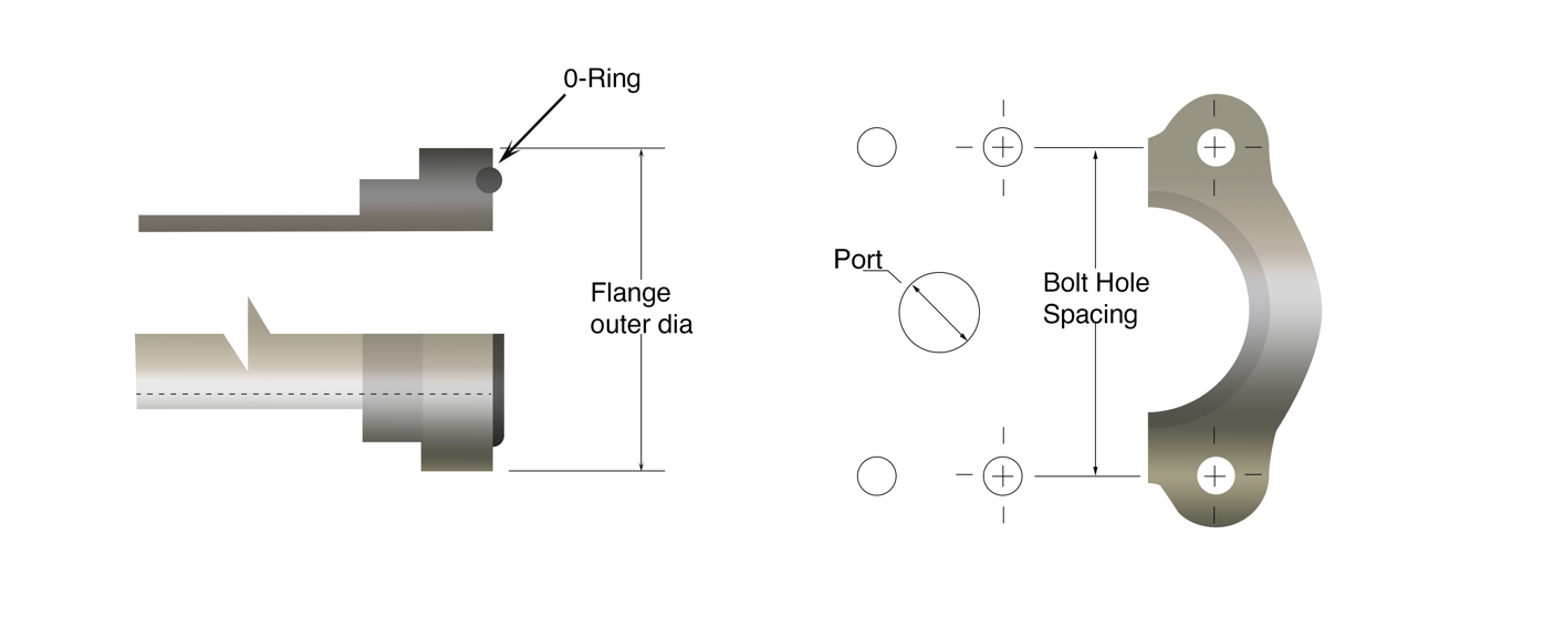
Precise estimation of four-bolt flanges At, the outset, A caliper can be used to quantify the accurate width of the bolt. Once you are done with that, the next step should be measuring the spacing from pivot to pivot of the bolt holes while taking into consideration, the farthest spacing. Flanges are used to connect pipes and other equipment in the application. While designing and installing a fluid piping system, flange dimensions should also be taken into consideration. The diameter of flange face, along with diameter of the outside rim and pipe measurements etc. should be calculated.
Dash numbers In order to specify the sizes of fluid joints and canals, the dash numbers are the abbreviations used for specific sizes of fluid joints and canals, and these are mostly used when ordering some parts of the piping system. The denominator is mostly not considered, while undergoing dash identification number of a pipe or tube, and hence identification is carried out by using numerator as a deciding factor. For example, 8/16″ or 1/2″ equates to size -8.
Tidbit: Dash numbers are nominal/used for identification. Since, for metric measurements, dash numbers are not applicable as they give the literal dimension of the pipe.
Hydraulic fittings from the United States.
The use of connectors and ports in America has urged industries to make connectors for fluid piping systems, car hydraulic systems. American made hydraulic cylinders and other application require tools for their piping, some of the fittings used and made in the United States are as follows.
National Pipe Tapered Fuel
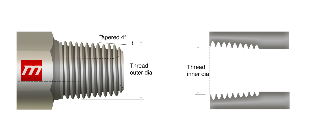
National Pipe Taper Fuel (NPTF) is also called Dry seal American National Standard Taper Pipe Thread. It is designed in such a way to give a more leak-free seal without the use of PTFE tape (often referred to by the popular brand name “Teflon”) or another encapsulant material. NPTF strings have a similar fundamental shape yet with peak and root statures adapted to an impedance fit, wiping out the spiral spillage path. In NPTF, the two opposite strings, male and female, connect and the two are mated together and hance a mechanical seal is formed. This makes a dry seal thread with one narrow end of string closely netted with the narrow-threaded hole. If additional sealing is required, Teflon and pipe dope can be applied. This connection for hydraulic applications such as usual hydraulic cylinders, 6-inch bore hydraulic cylinders, 4-inch hydraulic cylinders are not recommended irrespective of the widely accepted use in liquid piping systems. NPTF string attaches are intended to interfere with peak of the mating string, which makes a mechanical seal through string structure disfigured while assembling.
These fittings have “tapered” threads, tapered thread is essential in making mechanical seals and leakproof installation. During installation, the friction created while creating a seal, the metal surfaces may wear up. Therefore, using a lubricant or sealant is crucial to let the moving and rotating parts, work smoothly and efficiently. One example of the beat overall thread sealant used for various applications and fluid systems is gasoila which includes PTFE.
Cooling systems for instance chillers and heat exchangers mostly use these fittings.
Tidbit: NPTF and BSPT both the connectors appear similar but neither one of them can be used as a replacement for the other.
IS (inch size)
DS(dash size)
TPI (threads per inch)
MT (male thread O.D. in)
FT (female thread O.D. in)
1/8
-2
27
13/32
0.41
3/8
0.38
1/4
-4
18
17/32
0.54
1/2
0.49
3/8
-6
18
11/16
0.68
5/8
0.63
1/2
-8
14
27/32
0.84
25/32
0.77
3/4
-12
14
1-1/16
1.05
1
0.98
1
-16
11-1/2
1-5/16
1.32
1-1/4
1.24
1-1/4
-20
11-1/2
1-21/32
1.66
1-19/32
1.58
1-1/2
-24
11-1/2
1-29/32
1.90
1-13/16
1.82
2
-32
11-1/2
2-3/8
2.38
2-5/16
2.30
National Pipe straight mechanical (NPSM)
A metal seal is created when the male part with 300 internal seat and female part with 300 inverted seats are mated and a connection is made. The connection between them is of mechanical sort as it resists mechanical pullout during the pullout test. These fittings are useful as they consist of a tapered seat which is responsible for reducing leaks on fluid piping systems. Metric compression fittings poses a cutting ring design, this specific property of these fittings is what reduces the vibrations impact on fluid piping and hydraulic systems. These are efficient, reliable, and durable fittings. Moreover, these offer resistant against corrosion as well which makes it even more efficient.
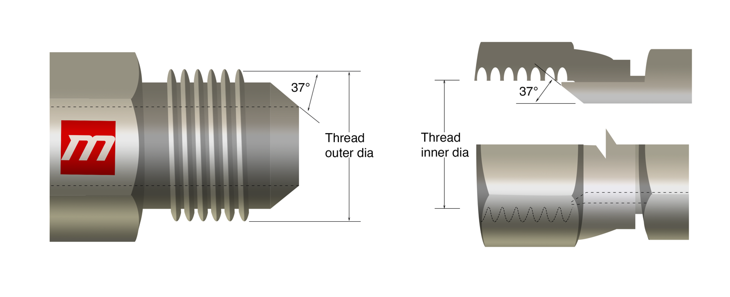
JIC 37° Flare
A flare fitting requires a tube end which is flared; therefore, some altering is done for installation with the help of tools. Uneven and irregular flaring of tubes reduces efficiency and causes invariance as it causes cracks on the pipes and tubes. In order to prevent sealing surface for being irregular and diverging, proper control and supervision should be taken to avoid inconvenient situations. JIC fittings are mostly used where high pressure is involved, particularly in fuel piping or fluid piping. Fitting, flare nut, and sleeves are the components that make tubing system of JIC. Hydraulic applications use these fittings; this connection consists of 37º flare seat along with straight strings for both the opposite male or female of the particular attachment. The flare seats of the male and female seal together During the fusion of the straight strings, both the flare seats of the male and female, are seal together. The straight strings are connected in mechanical manner. Moreover, JIC are generally less expensive. It uses a straight thread according to the unified thread standard.
JIC 37 flare is similar to JIC AN 37 but the latter one is more expensive, almost triple the amount of first one. However, it is quite a task to differentiate between the two visually but can be identified by the way they are written.
IS (inch size)
DS(dash size)
TS(thread size)
MT (male thread O.D. in)
FT (female thread O.D. in)
1/8
-2
5/16 -24
5/16
0.31
9/32
0.27
3/16
-3
3/8 -24
3/8
0.38
11/32
0.34
1/4
-4
7/16 -20
7/16
0.44
13/32
0.39
5/16
-5
1/2 -20
1/2
0.50
15/32
0.45
3/8
-6
9/16 -18
9/16
0.56
17/32
0.51
1/2
-8
3/4 -16
3/4
0.75
11/16
0.69
5/8
-10
7/8 -14
7/8
0.88
13/16
0.81
3/4
-12
1-1/16 -12
1-1/16
1.06
1
0.98
7/8
-14
1-3/16 -12
1-3/16
1.19
1-1/8
1.10
1
-16
1-5/16 -12
1-5/16
1.31
1-1/4
1.23
1-1/4
-20
1-5/8 -12
1-5/8
1.63
1-9/16
1.54
1-1/2
-24
1-7/8 -12
1-7/8
1.88
1-13/16
1.79
2
-32
2-1/2 -12
2-1/2
2.50
2-7/16
2.42
SAE 45° Flare
This is a flare fitting which uses metal tubing particularly brass tubing for SAE. Low pressure automotive piping applications for example refrigerants with low- pressure including hydro-fluorocarbons, chlorofluorocarbons etc. use these kinds of fittings. . A strong mechanical connection is formed by combining the strings of both joints having a 45° flare seat. long nut in these flare fittings resists vibrations. Its temperature ranges generally from almost -65F to 250F. It works well for high pressure applications. The metal sealing resists pullout during the pullout test when a tiny part of equipment is attached to the fitting and then picked outward upon the suitable stress. This determines that these fittings are strong and suitable for mechanical applications.
Tidbit: Seating angles of SAE J514 do not match SAE 45º regardless of the fact the both these flare threads look identical.
Tidbit: SAE 45° F and JIC 37° Flare connectors seem identical, with an exception of the angle.
IS (inch size)
DS(dash size)
TS(thread size)
MT (male thread O.D. in)
FT (female thread O.D. in)
1/8
-2
5/16 -24
5/16
0.31
9/32
0.27
3/16
-3
3/8 -24
3/8
0.38
11/32
0.34
1/4
-4
7/16 -20
7/16
0.44
13/32
0.39
5/16
-5
1/2 -20
1/2
0.50
15/32
0.45
3/8
-6
5/8 -18
5/8
0.63
9/16
0.57
1/2
-8
3/4 -16
3/4
0.75
11/16
0.69
5/8
-10
7/8 -14
7/8
0.88
13/16
0.81
3/4
-12
1-1/16 -14
1-1/16
1.06
1
0.99
7/8
-14
1-1/4 -12
1-1/4
1.25
1-5/32
1.16
1
-16
1-3/8 -12
1-3/8
1.38
1-9/32
1.29
SAE Straight Thread O-ring
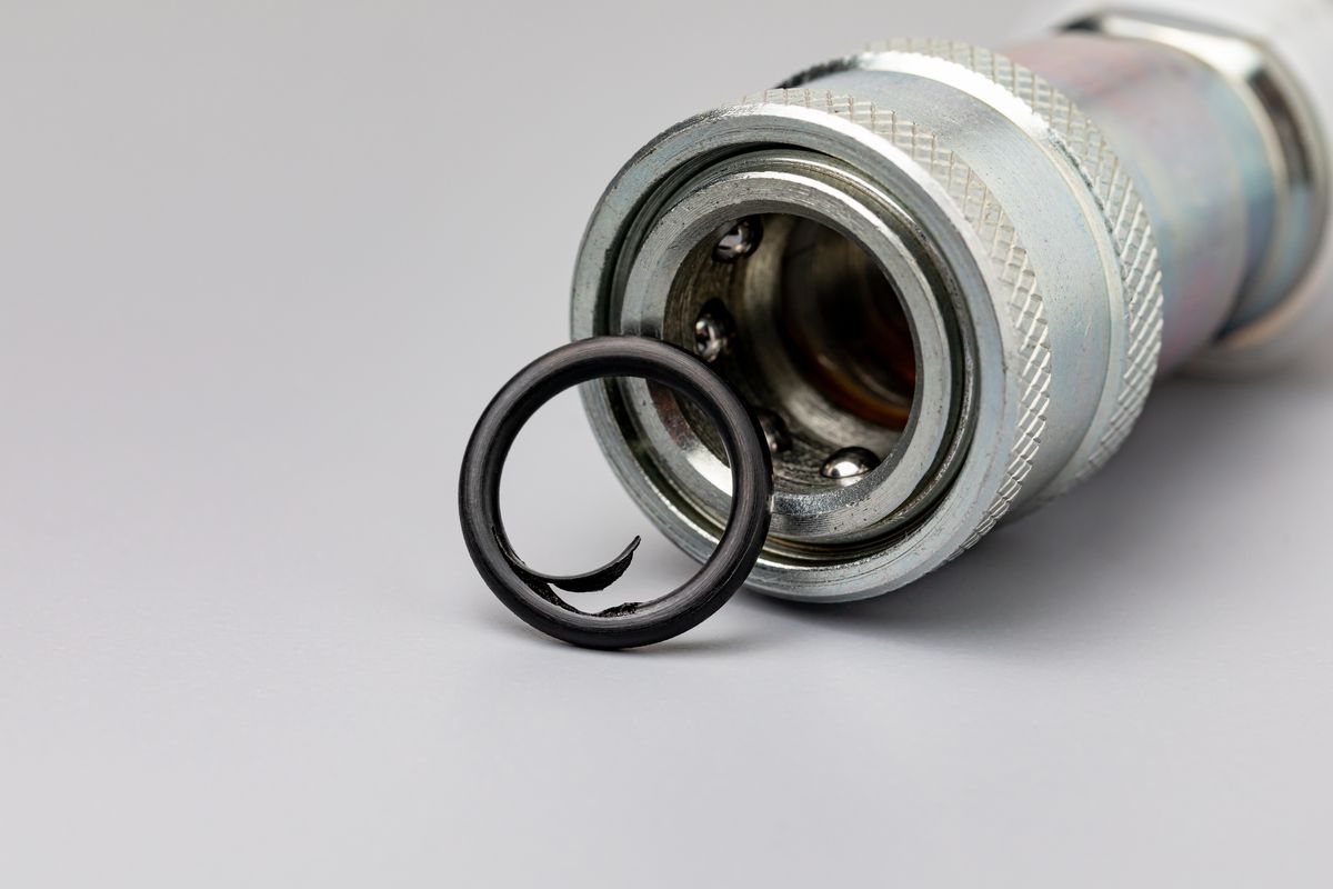
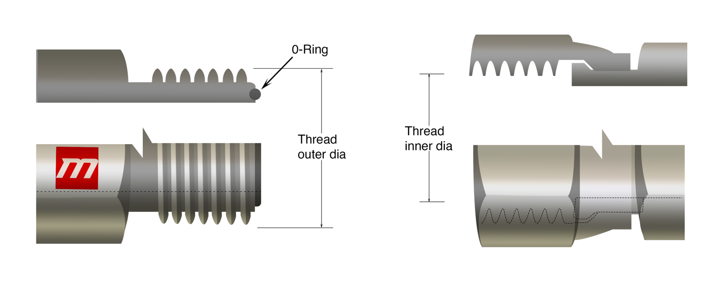
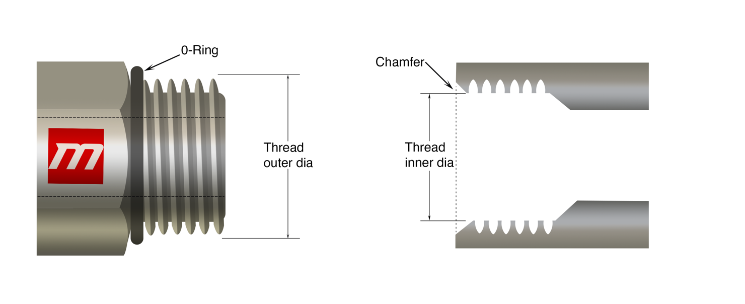
SAE Straight Thread O-ring or O-Ring Boss (ORB) is a multipurpose thread which works well for both medium and high-pressure hydraulic applications. O-Ring Boss has female port which consists of a face seal, straight thread and a chamfer whereas a straight thread and an O-ring makes up the male port. The O-ring is pressed into the chamfer in order to form the seal. Both the opposite male and female threads are attached firmly to build up a connection which is mechanically strong. High pressure hydraulic applications and systems use this connection usually. The male thread contains an O-ring at the base which mates with a chamfer machined into the female counterpoint, which makes this thread type ideal for non-leak applications. Instead of metal seal, SAE provides sealing by the use of O-Rings. These fittings are used to ensure control and retention. Moreover, if we compare these fittings with the NPT, then its evident that SAE are more efficient, easy to access, safe to install and much easier to maintain and reconstruct. Unlike other metal fittings, O-Ring fittings are expensive, hence proper supervision and care must be taken so that these fittings don’t get damaged. Leaks can be prevented be using the correct O-Ring type and not using the one that has been damaged or disfigured.
SAE when compared to compression fittings, also offer advantage because this fitting doesn’t have narrow torque. Narrow torque range is usually responsible for disorientation, leaks and irregularity.
IS (inch size)
DS(dash size)
TS (thread size)
MT (male thread O.D. in)
FT (female thread O.D. in)
1/8
-2
5/16 -24
5/16
0.31
9/32
0.27
3/16
-3
3/8 -24
3/8
0.38
11/32
0.34
1/4
-4
7/16 -20
7/16
0.44
13/32
0.39
5/16
-5
1/2 -20
1/2
0.50
15/32
0.45
3/8
-6
9/16 -18
9/16
0.56
17/32
0.51
1/2
-8
3/4 -16
3/4
0.75
11/16
0.69
5/8
-10
7/8 -14
7/8
0.88
13/16
0.81
3/4
-12
1-1/16 -12
1-1/16
1.06
1
0.98
7/8
-14
1-3/16 -12
1-3/16
1.19
1-1/8
1.10
1
-16
1-5/16 -12
1-5/16
1.31
1-1/4
1.23
1-1/4
-20
1-5/8 -12
1-5/8
1.63
1-9/16
1.54
1-1/2
-24
1-7/8 -12
1-7/8
1.88
1-13/16
1.79
2
-32
2-1/2 -12
2-1/2
2.50
2-7/16
2.42
Flareless Compression Fittings
A compression fitting is made up of three main parts. One of the components is a threaded nut, which, when tightened causes the ferrule to compress, this process causes it to conform to the tube’s circumference. Proper orientation of all the parts, more strictly ferrule, is crucial. During the installation of these fittings, no other equipment is used usually. Pressure maintenance from higher to lower and availability of the fitting in variable shapes, sizes and materials makes it the moat efficient one but these fitting lack these two properties. Moreover, for systems and application dealing with vibrations and other dynamic forces, these are not a good choice
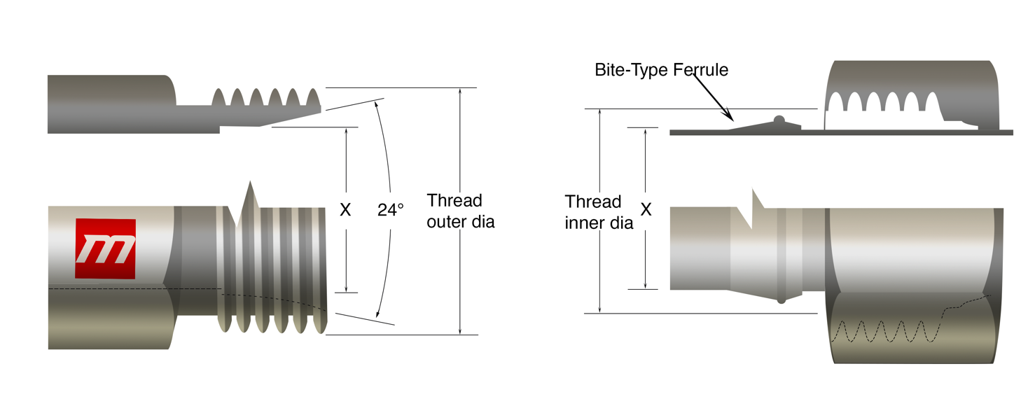
Flareless fittings are well known because they are convenient to use and are durable and reliable and are used all over the world. These fittings consist of a connection with a 3-piece design that contains a Nut, Ferrule (Sleeve), and the Body. These are used in places where there is fluctuating pressure and its thus used for higher pressure hydraulic systems. A 240 seat along a straight thread and a compression sleeve also along with a a straight thread for male and female connectors respectively. The 24O seat and the compression sleeve forms the seal for male half whereas for female part a tube, strong female bolt and sleeve mesh together. With the female half, the seal forms between the tubing and compression sleeve. To build a mechanically strong bond both threads are netted jointly.
IS (inch size)
DS(dash size)
TS (thread size)
MT (male thread O.D. in)
FT (female thread O.D. in)
1/8
-2
1/8 -28
3/8
0.38
11/32
0.35
1/4
-4
1/4 -19
33/64
0.52
15/32
0.47
3/8
-6
3/8 -19
21/32
0.65
19/32
0.60
1/2
-8
1/2 -14
13/16
0.82
3/4
0.75
5/8
-10
5/8 -14
7/8
0.88
13/16
0.80
3/4
-12
3/4 -14
1-1/32
1.04
31/32
0.97
1
-16
1 – 11
1-5/16
1.30
1-7/32
1.22
1-1/4
-20
1-1/4 -11
1-21/32
1.65
1-9/16
1.56
1-1/2
-24
1-1/2 -11
1-7/8
1.88
1-25/32
1.79
2
-32
2 -11
2-11/32
2.35
2-1/4
2.26
IS (inch size)
DS(dash size)
TS (thread size)
MT (male thread O.D. in)
FT (female thread O.D. in)
1/8
-2
1/8 -28
3/8
0.38
11/32
0.35
1/4
-4
1/4 -19
33/64
0.52
15/32
0.47
3/8
-6
3/8 -19
21/32
0.65
19/32
0.60
1/2
-8
1/2 -14
13/16
0.82
3/4
0.75
5/8
-10
5/8 -14
7/8
0.88
13/16
0.80
3/4
-12
3/4 -14
1-1/32
1.04
31/32
0.97
1
-16
1 – 11
1-5/16
1.30
1-7/32
1.22
1-1/4
-20
1-1/4 -11
1-21/32
1.65
1-9/16
1.56
1-1/2
-24
1-1/2 -11
1-7/8
1.88
1-25/32
1.79
2
-32
2 -11
2-11/32
2.35
2-1/4
2.26
IS (inch size)
DS(dash size)
TS (thread size)
MT (male thread O.D. in)
FT (female thread O.D. in)
1/8
-2
1/8 -28
3/8
0.38
11/32
0.35
1/4
-4
1/4 -19
33/64
0.52
15/32
0.47
3/8
-6
3/8 -19
21/32
0.65
19/32
0.60
1/2
-8
1/2 -14
13/16
0.82
3/4
0.75
5/8
-10
5/8 -14
7/8
0.88
13/16
0.80
3/4
-12
3/4 -14
1-1/32
1.04
31/32
0.97
1
-16
1 – 11
1-5/16
1.30
1-7/32
1.22
1-1/4
-20
1-1/4 -11
1-21/32
1.65
1-9/16
1.56
1-1/2
-24
1-1/2 -11
1-7/8
1.88
1-25/32
1.79
2
-32
2 -11
2-11/32
2.35
2-1/4
2.26
IS (inch size)
DS(dash size)
TPI (threads per inch)
MT (male thread O.D. in)
FT (female thread O.D. in)
1/8
-2
27
13/32
0.41
3/8
0.38
1/4
-4
18
17/32
0.54
1/2
0.49
3/8
-6
18
11/16
0.68
5/8
0.63
1/2
-8
14
27/32
0.84
25/32
0.77
3/4
-12
14
1-1/16
1.05
1
0.98
1
-16
11-1/2
1-5/16
1.32
1-1/4
1.24
1-1/4
-20
11-1/2
1-21/32
1.66
1-19/32
1.58
1-1/2
-24
11-1/2
1-29/32
1.90
1-13/16
1.82
2
-32
11-1/2
2-3/8
2.38
2-5/16
2.30
IS (inch size)
DS(dash size)
TS(thread size)
MT (male thread O.D. in)
FT (female thread O.D. in)
1/8
-2
5/16 -24
5/16
0.31
9/32
0.27
3/16
-3
3/8 -24
3/8
0.38
11/32
0.34
1/4
-4
7/16 -20
7/16
0.44
13/32
0.39
5/16
-5
1/2 -20
1/2
0.50
15/32
0.45
3/8
-6
9/16 -18
9/16
0.56
17/32
0.51
1/2
-8
3/4 -16
3/4
0.75
11/16
0.69
5/8
-10
7/8 -14
7/8
0.88
13/16
0.81
3/4
-12
1-1/16 -12
1-1/16
1.06
1
0.98
7/8
-14
1-3/16 -12
1-3/16
1.19
1-1/8
1.10
1
-16
1-5/16 -12
1-5/16
1.31
1-1/4
1.23
1-1/4
-20
1-5/8 -12
1-5/8
1.63
1-9/16
1.54
1-1/2
-24
1-7/8 -12
1-7/8
1.88
1-13/16
1.79
2
-32
2-1/2 -12
2-1/2
2.50
2-7/16
2.42
IS (inch size)
DS(dash size)
TS(thread size)
MT (male thread O.D. in)
FT (female thread O.D. in)
1/8
-2
5/16 -24
5/16
0.31
9/32
0.27
3/16
-3
3/8 -24
3/8
0.38
11/32
0.34
1/4
-4
7/16 -20
7/16
0.44
13/32
0.39
5/16
-5
1/2 -20
1/2
0.50
15/32
0.45
3/8
-6
5/8 -18
5/8
0.63
9/16
0.57
1/2
-8
3/4 -16
3/4
0.75
11/16
0.69
5/8
-10
7/8 -14
7/8
0.88
13/16
0.81
3/4
-12
1-1/16 -14
1-1/16
1.06
1
0.99
7/8
-14
1-1/4 -12
1-1/4
1.25
1-5/32
1.16
1
-16
1-3/8 -12
1-3/8
1.38
1-9/32
1.29
IS (inch size)
DS(dash size)
TS (thread size)
MT (male thread O.D. in)
FT (female thread O.D. in)
1/8
-2
5/16 -24
5/16
0.31
9/32
0.27
3/16
-3
3/8 -24
3/8
0.38
11/32
0.34
1/4
-4
7/16 -20
7/16
0.44
13/32
0.39
5/16
-5
1/2 -20
1/2
0.50
15/32
0.45
3/8
-6
9/16 -18
9/16
0.56
17/32
0.51
1/2
-8
3/4 -16
3/4
0.75
11/16
0.69
5/8
-10
7/8 -14
7/8
0.88
13/16
0.81
3/4
-12
1-1/16 -12
1-1/16
1.06
1
0.98
7/8
-14
1-3/16 -12
1-3/16
1.19
1-1/8
1.10
1
-16
1-5/16 -12
1-5/16
1.31
1-1/4
1.23
1-1/4
-20
1-5/8 -12
1-5/8
1.63
1-9/16
1.54
1-1/2
-24
1-7/8 -12
1-7/8
1.88
1-13/16
1.79
2
-32
2-1/2 -12
2-1/2
2.50
2-7/16
2.42
O-Ring Face Seal
The O-ring face seal (ORFS) is among the most handy and reliable option for hydraulic connections such as hydraulic cylinders and pumps etc. This connection provides a seal which is authentic and well- founded because of its elasticized seal and thus provides leak- free connection. These seals prevent almost all leaks if it is used properly.This connection can be used for applications with high pressure because it offers great hindrance to leakage. An O-ring with a straight thread connection builds male part whereas a surface held flat with the help of a machine connecting with a straight thread builds the female part. The female half has a machined flat. When. When the O-ring on the male part is pushed onto the flat surface seat on the female part, a seal is made. A nut named swivel is responsible for holding tight the connection. A tailpiece is welded to the tube or hose permanently, and hence the seal is created. An advantage of these fittings is that, they can be disfigured and rearranged any time and this fitting system is also regarded as no clearance fitting system because there is no need to pull strings for fitting seating. Arrangement and dis arrangement can be done by tightening the torque which is recommended or by interchanging the fitting. Another quality of this system is its chock absorbing quality, therefore for application which are exposed to vibrations, O-ring fittings are recommended.
IS (inch size)
DS(dash size)
TS (thread size)
MT (male thread O.D. in)
FT (female thread O.D. in)
1/4
-4
9/16 -18
9/16
0.56
17/32
0.51
3/8
-6
11/16 -16
11/16
0.69
5/8
0.63
1/2
-8
13/16 -16
13/16
0.82
3/4
0.75
5/8
-10
1 -14
1
1.00
15/16
0.93
3/4
-12
1-3/16 -12
1-3/16
1.19
1-1/8
1.11
1
-16
1-7/16 -12
1-7/16
1.44
1-3/4
1.36
1-1/4
-20
1-11/16 -12
1-11/16
1.69
1-5/8
1.61
1-1/2
-24
2 -12
2
2.00
1-15/16
1.92
SAE Inverted Flare
SAE inverted flare (SAE J512) has its usage in hydraulic brakes, power steering, fuel lines and transmission etc. It has great application in automotive systems, this flare connection has a a 450-seat flared male tubing and a 420-seat connection of male part which is machined. However, there is a sealing surface on the female side due to, what happens to be a 420 seat on the female side. The threads connect together to make a mechanically strong bond.
IS (inch size)
DS(dash size)
TS (thread size)
MT (male thread O.D. in)
FT (female thread O.D. in)
1/8
-2
5/16 -28
5/16
0.31
9/32
0.27
3/16
-3
3/8 -24
3/8
0.38
11/32
0.34
1/4
-4
7/16 -24
7/16
0.44
13/32
0.39
5/16
-5
1/2 -20
1/2
0.50
15/32
0.45
3/8
-6
5/8 -18
5/8
0.63
9/16
0.57
7/16
-7
11/16 -18
11/16
0.69
5/8
0.63
1/2
-8
3/4 -18
3/4
0.75
23/32
0.70
5/8
-10
7/8 -18
7/8
0.88
13/16
0.81
3/4
-12
1-1/16 -16
1-1/16
1.06
1
1.00
Four-Bolt Flange
The 4-bolt flanged bearing units have direction that can be moved and adjusted to better accommodate long shafts.Four-Bolt Flange can be available for standard inch and metric measurements either with cast iron or thermo-plastic housing etc. Commonly found in fluid power systems, the Four-Bolt Flange shows exceptional performance when it is connected to a 1/2″ to 3″ hose or canal.
The O-ring and the smooth face build a seal via male and female parts respectively. A seal is created between O-ring and the female port while the O-ring seats on the ring groove of the male part. Two clamp halves, held by four bolts, The connection is held strongly with the help of bolts and clamp halves, both four and two respectively.
These are available in two pressure groups:
Standard pressure
High pressure
IS (inch size)
DS(dash size)
Bolt Spacing
Flange O.D.
Bolt Spacing
Flange O.D.
1/2
-8
1-1/2
1-3/16
1-19/32
1-1/4
3/4
-12
1-7/8
1-1/2
2
1-5/8
1
-16
2-1/16
1-3/4
2-1/4
1-7/8
1-1/4
-20
2-5/16
2
2-5/8
2-1/8
1-1/2
-24
2-3/4
2-3/8
3-1/8
2-1/2
2
-32
3-1/16
2-13/32
3-13/16
3-1/8
2-1/2
-40
3-1/2
3-5/16
n/a
n/a
3
-48
4-3/16
4
n/a
n/a
O-Ring Pilot Threads
O-Ring Pilot Threads are handy and convenient and have various types of sizes, shapes, combinations and materials. The ORB fittings are made in such a way that they resist complications associated with over-assembly. It is easily maintainable and re-usable as well. O-Rong pilot threads come in both adjustable and non-adjustable model. ORB fittings have vast applications in numerous fields including air conditioning services both automotive and commercial. There is a pilot in both the opposite male female parts of various range. The O-ring is made to compress to make a seal. A strong mechanical bond is formed when threads are joined tightly.
IS
DS
MT
FT
TS
Thread O.D.
TS
Thread I.D.
3/8
-6
5/8 -18
5/8
5/8 -18
9/16
1/2
-8
3/4 -18
3/4
3/4 -16
11/16
5/8
-10
7/8 -18
7/8
7/8 -14
13/16
3/4
-12
1-1/16 -16
1-1/16
1-1/16 -14
1
IS
DS
Long pilot
Short pilot
Bead O.D.(in)
Pilot Length (in)
Bead O.D.(in)
Pilot Length (in)
3/8
-6
0.52
0.28
0.52
0.19
1/2
-8
0.64
0.39
0.64
0.19
5/8
-10
0.77
0.39
0.77
0.19
3/4
-12
0.91
0.39
0.91
0.19
Worldwide Connections
Fluid ports and connectors are a necessity all over the world as they are used in several applications. From expensive tools to cheap and affordable ones used for fluid piping systems, short hydraulic cylinders and cascade hydraulic cylinders etc. Therefore, some of the fittings manufactured and exported internationally are listed and briefly explained as follows;
British Standard Pipe
British connections are available in two categories;
British Standard Pipe Parallel (BSPP)
British Standard Pipe Tapered (BSPT)
British Standard Pipe
It is an internationally adopted set of standards in which fitting and pipes are joined and sealed and threads are matted, by mating an external thread with an internal thread. Except For North America, it is one one the most widely used standard procedures in plumbing and fluid-piping systems. It is used for plumbing as it is low-pressured but not recommended for hydraulic systems of medium and high-pressure range.
British Standard Pipe Parallel
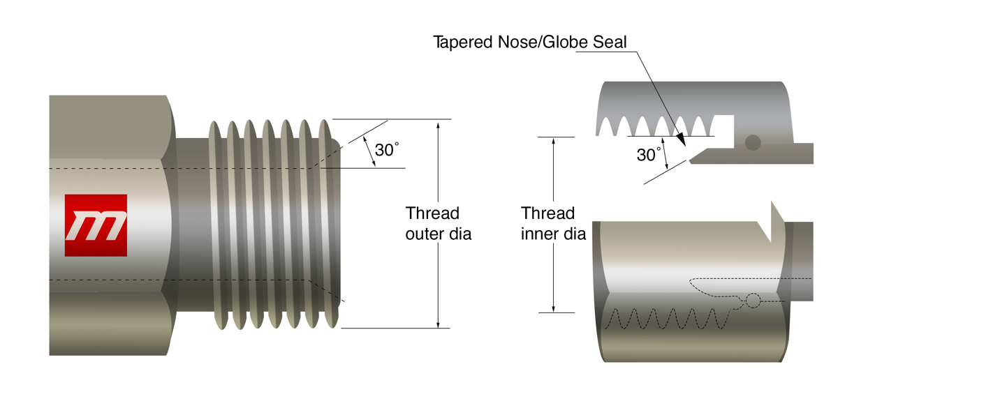
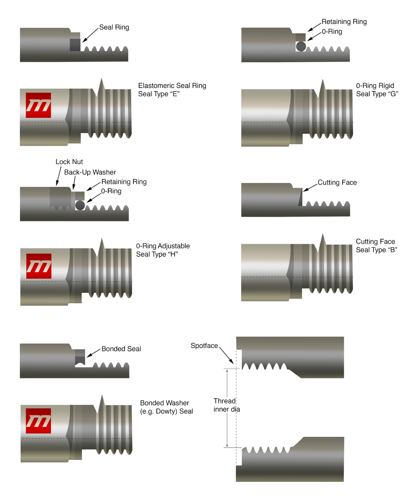
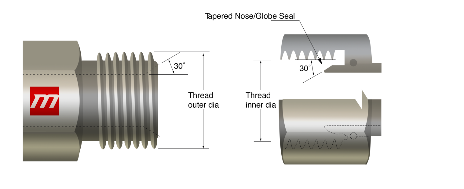
A seal is made with narrow nose of the swivel from female side and a 300-seat male end. For sealing process, an affix seal ring is used in BSPP. The ring seal is interposed in the middle of a shoulder and the front of the male and female fitting respectively and is pressed set up. BSPP pressure checks have a more extended male string and utilize a copper squash washer that is crushed in the middle of the lower part of the external fitting and the lower part of the internal. BSPP opening framing a pressing factor tight seal. No string sealant is expected to frame a seal.
Tidbit:
The male end of it is similar to NPSM male, however they have different pitches of threads and thus cannot be replaced.
IS (inch size)
DS(dash size)
TS (thread size)
MT (male thread O.D. in)
FT (female thread O.D. in)
1/8
-2
1/8 -28
3/8
0.38
11/32
0.35
1/4
-4
1/4 -19
33/64
0.52
15/32
0.47
3/8
-6
3/8 -19
21/32
0.65
19/32
0.60
1/2
-8
1/2 -14
13/16
0.82
3/4
0.75
5/8
-10
5/8 -14
7/8
0.88
13/16
0.80
3/4
-12
3/4 -14
1-1/32
1.04
31/32
0.97
1
-16
1 – 11
1-5/16
1.30
1-7/32
1.22
1-1/4
-20
1-1/4 -11
1-21/32
1.65
1-9/16
1.56
1-1/2
-24
1-1/2 -11
1-7/8
1.88
1-25/32
1.79
2
-32
2 -11
2-11/32
2.35
2-1/4
2.26
IS (inch size)
DS(dash size)
TS (thread size)
MT (male thread O.D. in)
FT (female thread O.D. in)
1/8
-2
1/8 -28
3/8
0.38
11/32
0.35
1/4
-4
1/4 -19
33/64
0.52
15/32
0.47
3/8
-6
3/8 -19
21/32
0.65
19/32
0.60
1/2
-8
1/2 -14
13/16
0.82
3/4
0.75
5/8
-10
5/8 -14
7/8
0.88
13/16
0.80
3/4
-12
3/4 -14
1-1/32
1.04
31/32
0.97
1
-16
1 – 11
1-5/16
1.30
1-7/32
1.22
1-1/4
-20
1-1/4 -11
1-21/32
1.65
1-9/16
1.56
1-1/2
-24
1-1/2 -11
1-7/8
1.88
1-25/32
1.79
2
-32
2 -11
2-11/32
2.35
2-1/4
2.26
IS (inch size)
DS(dash size)
TS (thread size)
MT (male thread O.D. in)
FT (female thread O.D. in)
1/8
-2
1/8 -28
3/8
0.38
11/32
0.35
1/4
-4
1/4 -19
33/64
0.52
15/32
0.47
3/8
-6
3/8 -19
21/32
0.65
19/32
0.60
1/2
-8
1/2 -14
13/16
0.82
3/4
0.75
5/8
-10
5/8 -14
7/8
0.88
13/16
0.80
3/4
-12
3/4 -14
1-1/32
1.04
31/32
0.97
1
-16
1 – 11
1-5/16
1.30
1-7/32
1.22
1-1/4
-20
1-1/4 -11
1-21/32
1.65
1-9/16
1.56
1-1/2
-24
1-1/2 -11
1-7/8
1.88
1-25/32
1.79
2
-32
2 -11
2-11/32
2.35
2-1/4
2.26
British Standard Pipe Tapered
The seal is formed in the threads when the narrow external fitting connects with a narrow internal fitting.
In this fitting system, it is advisable to use both male and female threads properly tapered. This helps in preventing the spiral leakage.
Tidbit:
Although the size and thread form of BSPT male end is similar to the NPTF, however, it is not feasible for these to reciprocate.
IS (inch size)
DS(dash size)
TS (thread size)
MT (male thread O.D. in)
FT (female thread O.D. in)
1/8
-2
1/8 -28
3/8
0.38
11/32
0.35
1/4
-4
1/4 -19
33/64
0.52
15/32
0.47
3/8
-6
3/8 -19
21/32
0.65
19/32
0.60
1/2
-8
1/2 -14
13/16
0.82
3/4
0.75
5/8
-10
5/8 -14
7/8
0.88
13/16
0.80
3/4
-12
3/4 -14
1-1/32
1.04
31/32
0.97
1
-16
1 – 11
1-5/16
1.30
1-7/32
1.22
1-1/4
-20
1-1/4 -11
1-21/32
1.65
1-9/16
1.56
1-1/2
-24
1-1/2 -11
1-7/8
1.88
1-25/32
1.79
2
-32
2 -11
2-11/32
2.35
2-1/4
2.26
British Standard Pipe Parallel Threads with Flat Face Port
The parallel threads in this connection adapt to several rings or washers in order to make a seal. The interior end comprising of a smooth flat surface and the exterior end join to form a seal.
IS (inch size)
DS(dash size)
TS (thread size)
MT (male thread O.D. in)
FT (female thread O.D. in)
1/8
-2
1/8 -28
3/8
0.38
11/32
0.35
1/4
-4
1/4 -19
33/64
0.52
15/32
0.47
3/8
-6
3/8 -19
21/32
0.65
19/32
0.60
1/2
-8
1/2 -14
13/16
0.82
3/4
0.75
5/8
-10
5/8 -14
7/8
0.88
13/16
0.80
3/4
-12
3/4 -14
1-1/32
1.04
31/32
0.97
1
-16
1 – 11
1-5/16
1.30
1-7/32
1.22
1-1/4
-20
1-1/4 -11
1-21/32
1.65
1-9/16
1.56
1-1/2
-24
1-1/2 -11
1-7/8
1.88
1-25/32
1.79
2
-32
2 -11
2-11/32
2.35
2-1/4
2.26
Metric Threads with Flat Face Port
The parallel threads in this connection adapt to several rings or washers in order to make a seal. The interior end comprising of a smooth flat surface and the exterior end join to form a seal.
MTS
MT
FT
M8 x 1.0
8
7
M10 x 1.0
10
9
M12 x 1.5
12
10.5
M14 x 1.5
14
12.5
M16 x 1.5
16
14.5
M18 x 1.5
18
16.5
M20 x 1.5
20
18.5
M22 x 1.5
22
20.5
M24 x 1.5
24
22.5
M26 x 1.5
26
24.5
M27 x 2.0
27
25
M33 x 2.0
33
31
M36 x 2.0
36
34
M42 x 2.0
42
40
M45 x 2.0
45
43
M48 x 2.0
48
46
Metric Port and Stud Ends
It consists of O-ring from male end and, a chamfer and a machined surface from female end, with a straight thread including in both. A seal is made when the male end O-Ring squeezes the female end on the chamfer.
The straight threads mesh to form A solid secure bond is formed, when straight threads are netted jointly. The nature of the bond is mechanical.
MTS
MT
FT (mm)
M8 x 1.0
8
7
M10 x 1.0
10
9
M12 x 1.5
12
10.5
M14 x 1.5
14
12.5
M16 x 1.5
16
14.5
M18 x 1.5
18
16.5
M22 x 1.5
22
20.5
M27 x 2.0
27
25
M33 x 2.0
33
31
M42 x 2.0
42
40
M48 x 2.0
48
46
M60 x 2.0
60
58
Metric 60° Cone
The male connector has a 60° recessed cone and a straight thread; the female has a straight thread as well, and a globe seal seat.
The recessed cone and tapered nose of the male and female end together form the seal.
Both ends let their threads net together for forming a strong mechanical bond. In hydraulic systems such type of connections is usual.
Pipe (mm)
MTS
MT (mm)
FT (mm)
6
M12 x 1.5
12
10.5
8
M14 x 1.5
14
12.5
10
M16 x 1.5
16
14.5
12
M18 x 1.5
18
16.5
15
M22 x 1.5
22
20.5
18
M26 x 1.5
26
24.5
22
M30 x 1.5
30
28.5
28
M38 x 1.5
38
36.5
35
M45 x 1.5
45
43.5
52
M52 x 1.5
52
50.5
Japanese Industrial Standard Flare
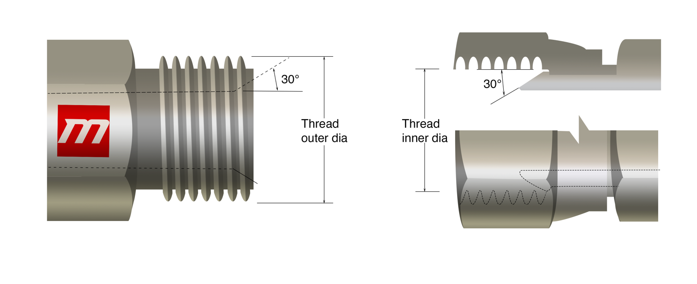
These fittings have flare ends. The tube end should not end up being uneven or irregular during flaring the end of tube, it renders the performs inefficient. Japanese standard fittings are available in large variety of dimensions. Fir installation purposes, proper calculation of threads should be done to ensure leak resistant connection. It consists of a 30 and a 300 seat both with a straight thread of male and female end respectively.
vThe 37° Flare connection resembles this connection but it has 30 seat dimensions and proportions similar to that of BSPP, that is the reason which distinguishes between this connection and the American 37° Flare.
IS (inch size)
DS(dash size)
TS (thread size)
MT (male thread O.D. in)
FT (female thread O.D. in)
1/8
-2
1/8 -28
3/8
0.38
11/32
0.35
1/4
-4
1/4 -19
33/64
0.52
15/32
0.47
3/8
-6
3/8 -19
21/32
0.65
19/32
0.60
1/2
-8
1/2 -14
13/16
0.82
3/4
0.75
5/8
-10
5/8 -14
7/8
0.88
13/16
0.80
3/4
-12
3/4 -14
1-1/32
1.04
31/32
0.97
1
-16
1 – 11
1-5/16
1.30
1-7/32
1.22
1-1/4
-20
1-1/4 -11
1-21/32
1.65
1-9/16
1.56
1-1/2
-24
1-1/2 -11
1-7/8
1.88
1-25/32
1.79
2
-32
2 -11
2-11/32
2.35
2-1/4
2.26
Komatsu 30° Flare
The measurement of Komatsu connection starts with estimating the outside diameter of male threads and inside diameter of female threads, after this the number of strings per inch or more precisely pitch of string is calculated using screw gauge also known as thread pitch gauge. The flare angle which is 30 should be checked and values must be compare with the chart to attain accurate measurement. It is a 30° seat parallel metric thread connection which is common on Komatsu equipment.
There exists a similarity between the JIS metric connection and the JIS 300 flare, the concluding one has thread dimensions similar to BSPP.
DS
MTS
MT (mm)
FT (mm)
-6
M18 x 1.5
18
16.5
-8
M22 x 1.5
22
20.5
-10
M24 x 1.5
24
22.5
-12
M30 x 1.5
30
28.5
-16
M33 x 1.5
33
31.5
-20
M36 x 1.5
36
34.5
-24
M42 x 1.5
42
40.5
Directional Control Valve Centers
Directional control valves are an important component in hydraulic systems, allowing operators to control the flow of fluid and the direction of movement in various hydraulic machinery. The center options of directional control valves refer to the configuration of the valve when the spool is in the neutral or centered position. There are four main directional control valve center options: open center, closed center, tandem center, and float center. Each has its own advantages and is suitable for different applications.
Four-way three-position hydraulic directional control valves come with four common valve center options:
Open Center:
In an open center configuration, the fluid flow returns to the reservoir when the valve is in the neutral position.
This type of center is common in applications where constant hydraulic power is not required and energy conservation is a priority.
Open center systems are typically more straightforward and cost-effective, making them suitable for applications like agricultural equipment.
Closed Center:
Closed center systems maintain constant pressure in the hydraulic system, even when the valve is in the neutral position.
The closed center design is more energy-efficient as it minimizes the need to circulate fluid back to the reservoir in neutral, which can be advantageous in applications where a consistent power supply is essential.
Closed center configurations are often found in industrial and mobile hydraulic systems, such as construction equipment and manufacturing machinery.
Tandem Center:
Tandem center valves feature a unique design that provides constant pressure while allowing fluid to circulate freely in the neutral position.
This configuration offers a compromise between the open and closed center options, providing both energy efficiency and the ability to redirect fluid flow as needed.
Tandem center valves are commonly used in applications that require a balance between energy conservation and quick response times, such as some types of mobile machinery.
Float Center
The float center configuration in directional control valves allows for unrestricted fluid flow between the working ports, allowing hydraulic actuators to move freely in response to external forces.
In the float center position, the valve permits hydraulic fluid to circulate freely, offering adaptability to external forces without building up pressure. This feature is particularly useful in applications where the hydraulic system needs to act as a passive participant, accommodating external forces such as gravity or manual input.
Float center valves find common use in mobile hydraulic machinery, providing flexibility and responsiveness to varying conditions without the need for active hydraulic power, making them suitable for scenarios where adaptability and fluid movement are essential.
Selecting the appropriate center option depends on the specific requirements of the hydraulic system and the application. Factors such as energy efficiency, response time, and the nature of the load being controlled play a significant role in determining the most suitable directional control valve center option for a given hydraulic system. Additionally, it’s crucial to consider the overall system design, including pump type, actuators, and other components, to ensure compatibility and optimal performance.
If you have any additional questions or need help choosing a control valve, do not hesitate to contact Magister Hydraulics customer service.
Maintaining a hydraulic system is important for its efficient and reliable operation. Here are some steps for effective hydraulic system maintenance:
1. Regular Inspection:
Conduct routine visual inspections of all components, including hoses, fittings, pumps, valves, and actuators.
Look for signs of leaks, wear, or damage. Address any issues immediately.
2. Check Hydraulic Fluid:
Monitor fluid levels regularly and top up as needed.
Inspect the hydraulic fluid for cleanliness and follow manufacturer recommendations for replacement intervals.
3. Inspect Hoses and Fittings:
Check hoses for abrasions, bulges, or leaks.
Tighten loose fittings and replace damaged hoses promptly.
4. Examine Pumps and Valves:
Listen for unusual noises or vibrations during operation.
Inspect pump and valve functionality regularly, and lubricate moving parts as recommended.
5. Monitor Pressure Levels:
Use pressure gauges to check system pressure.
Adjust pressure within recommended limits and investigate any abnormal fluctuations.
6. Clean Hydraulic Filters:
Replace or clean hydraulic filters according to the manufacturer’s guidelines.
Regularly check and maintain filters to prevent contaminants from entering the system.
7. Temperature Control:
Monitor the system’s temperature to prevent overheating.
Install cooling systems if necessary to maintain optimal operating temperatures.
8. Contingency Planning:
Develop a contingency plan for emergencies, including a quick response strategy and spare parts availability.
Train personnel on emergency procedures to minimize downtime.
9. Operator Training:
Provide training to operators on proper system usage and the importance of early issue detection.
Encourage operators to report any irregularities promptly.
10. Keep Records:
Maintain detailed maintenance logs, recording inspection dates, replacements, and any repairs performed.
Use the logs for predictive maintenance planning and as documentation for system history.
11. Follow Manufacturer Guidelines:
Follow the manufacturer’s recommendations for maintenance intervals, fluid types, and other specifications.
Consult the system’s manual for specific guidelines on maintenance procedures.
12. Professional Service:
Periodically schedule professional inspections and servicing by trained technicians.
Seek professional help for complex issues or if you are unsure about any maintenance procedure.
By consistently following these maintenance steps, you can ensure the longevity, efficiency, and reliability of your hydraulic system. Regular attention to detail will help prevent major issues and minimize downtime, ultimately saving on repair costs and optimizing system performance.
If you have any additional questions or need help choosing a control valve, do not hesitate to contact Magister Hydraulics customer service.