
How Hydraulic Valves Work
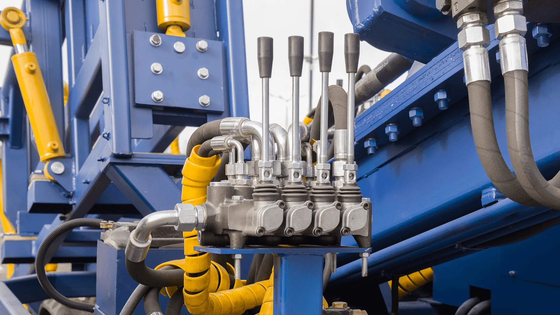
A hydraulic system operates by using pressurized fluid (usually oil) to transmit force. The pump generates pressure, sending the fluid through hoses and pipes to cylinders, motors, or actuators. Hydraulic valves are the control points in this circuit. By opening, closing, or partially restricting flow, they determine:
- When fluid moves,
- Where it goes, and
- At what pressure or speed it acts.
This precise regulation allows for smooth lifting, pushing, or rotating motions—essential for everything from excavators to injection-molding machines.
Main Types of Hydraulic Valves
Hydraulic valves fall into three main categories, each serving a distinct function.
1. Pressure Control Valves
These valves maintain or limit pressure in a hydraulic system to protect components from overload. Common examples include:
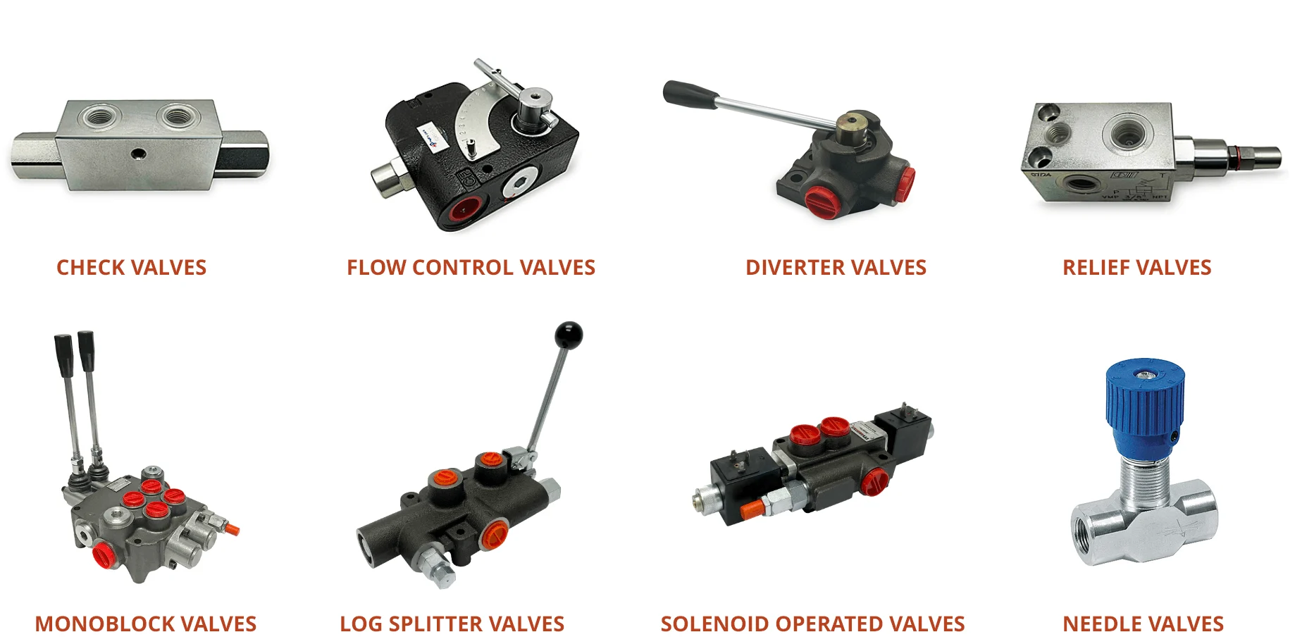
- Relief valves – prevent over-pressure by diverting excess fluid.
- Reducing valves – maintain a set downstream pressure.
- Sequence valves – control the order of operations between actuators.
- Counterbalance valves – hold loads in position and prevent drifting.
- Unloading valves – redirect flow when pressure reaches a preset limit.
2. Flow Control Valves
Flow control valves regulate the rate of fluid movement, which directly affects actuator speed. Key types include:
- Throttle valves – simple orifice-based flow restriction.
- Pressure-compensated valves – maintain constant flow despite pressure changes.
- Temperature-compensated valves – correct for viscosity changes as temperature varies.
- Priority valves – direct flow to essential functions first.
- Deceleration and divider valves – fine-tune motion and distribute flow between circuits.
3. Directional Control Valves
These valves route the fluid to different parts of the system. The simplest is a check valve, which allows flow in one direction only. More complex valves—like 4/3 directional control valves—have multiple ports and positions:
| Valve Position | Function |
|---|---|
| Neutral | All ports closed or recirculating to tank. |
| Extend | Fluid directed to extend the cylinder. |
| Retract | Fluid directed to retract the cylinder. |
Directional control valves may be on/off (binary) or proportional, allowing partial flow for smoother speed control. Servo valves are high-precision versions used in robotics and aerospace applications.
Actuation Methods
Hydraulic valves can be operated in several ways:
| Method | Description |
|---|---|
| Manual / Mechanical | Levers, pedals, or push-buttons directly move the spool. |
| Electrical / Solenoid | Electric current moves a plunger to shift the valve. Used for automation and remote control. |
| Hydraulic / Pneumatic Pilot | A small control valve uses pressurized fluid or air to actuate a larger main valve—ideal for high-pressure or hazardous environments. |
Key Components of a Hydraulic Valve
- Valve Body – main housing containing internal ports.
- Spool or Poppet – moves within the body to open or close flow paths.
- Actuator Shaft – transmits control force to the spool.
- Feedback Spindle – provides position feedback for accurate control.
- Seals and Rings – prevent internal leakage.
- Pilot Motor – operates the main valve under high pressure (if applicable).

Specifications to Consider
When selecting a hydraulic valve, engineers evaluate:
- Valve Type & Configuration: number of ports and positions (e.g., 4/3 valve).
- Operating Pressure Range: minimum and maximum working pressure.
- Flow Rate or Cv: the capacity to pass fluid (GPM / LPM).
- Port Size & Style: threaded, flanged, or manifold connections.
- Media Compatibility: type of hydraulic fluid—mineral oil, glycol, or bio-oil.
- Temperature Range: safe operating temperature limits.
- Actuation Voltage: for solenoid valves, specifies AC/DC control voltage.
- Mounting Type: line-mounted or sub-plate/manifold installation.
- Application: industry use—mobile hydraulics, manufacturing, aerospace, etc.
Materials and Construction
To endure constant high-pressure operation:
- Valve bodies are usually steel or cast iron.
- Internal moving parts use hardened and ground spools for wear resistance.
- Sealing materials are chosen based on the working fluid and temperature range.

Conclusion
Hydraulic valves are the control center of every hydraulic system—balancing precision, safety, and durability. From basic manual check valves to sophisticated electro-hydraulic servo valves, they make it possible to convert pressurized fluid energy into smooth, controllable mechanical motion.
Understanding their types, construction, and operation ensures safer, more efficient, and longer-lasting hydraulic machinery.