Synopsis
Acronyms
- TPI Threads per inch
- IS Inch size
- DS Dash size
- MT Male Thread O.D. (in)
- MT Female Thread O.D. (in)
- MTS Metric Thread Size
Brief Introduction
While looking for a port or a connector, searching around to find the most accurate fit that fulfills your piping needs accurately, is a tiresome task. The reason behind is the amazing variety of fluid connectors available, which makes it difficult to find the most precise one. The right connector requires thorough understanding of the application for which it is needed. The motion between fluid and the connector material needs to be searched up properly. Some properties of the fluid used, should be examined such as its viscosity and corrosiveness. It must be checked thoroughly that the fluid shows no signs of incompatibility with the materials used in the connector. Since connectors and joints have numerous applications in liquid channeling frameworks, you need to accurately distinguish them prior to adding or supplanting them on a cylinder, in a particular application. Connectors are availed for affixing all the components of the fluid-piping system. Several types of connectors are available in the market including threaded, flared, flanged, welded, brazed and cone connectors etc. Diverse tubing estimations and cylinder size are accessible like inch and metric estimations. However, while using hose, there is a single standard around the world. A particular fluid-piping system requires specific connectors and ports that fit to its needs. The type of connector used depends upon the type of hoses, pipes and tubes used. It also depends upon the pressure of fluid inside the piping.
Fluid flow rate and tube sizes required for the application are crucial. Since, the fluid pressure and velocity are eventually affected by the dimensions of tubes and hoses. The highest and lowest operating points for the pressure and temperature should be monitored. Ideal and reliable connector should maintain the seal at these optimum values. The piping system should be maintained for all kinds of situations any kind of vibration and thermal cycling for instance.
Makers use identifiers like ASME B1 .1 and ISO 261, to group the fundamental thread qualities: pitch, point, width, and structure. The SAE International, the DIN, SME and the British association are among the institutes developing these connectors and ports.
Recognition tools
In order to ensure smooth installation, connection and maintenance of the fluid ports and connectors, safe and reliable tools and equipment are required. The piping system should be maintained for all kinds of situations any kind of vibration and thermal cycling for instance. It is obvious that piping system works for transferring fluid materials from one pipe to the other, to ensure proper functioning of the application. However, to connect pipes, hoses, fluid pumps etc., fittings are used in order to join loop components. An application which doesn’t not require disconnection of its components, use fittings. Because continuous disconnection acts for leakage in the system. Fittings usually come in handy as they aren’t too pricey and various sorts of sizes, shapes and qualities of fittings are available in the market. The process of installing fittings and removing them afterwards from an application also requires tools and equipment.
Some of the tools used for installation purposes include:
Calipers:
These are used to measure dimensions or internal and external bores of strings or wires. Some of the calipers require manual adjustments before fitting for an accurate reading. Different types of calipers include:
- Inside calipers
- Outside calipers
- Divider calipers
- Odd leg calipers
- Vernier calipers
- Dial calipers
- Digital calipers.
All the above-mentioned caliper types are equally important for measuring the diameter of connectors and ports but here we will shed light on one of the types, which is vernier calipers; it consists of a main scale and a vernier scale. Firstly, zero error is checked to achieve accurate dimensions and it is removed by performing specific calculations. Zero error occurs when zero of the main scale does not coincide with the zero of the vernier scale. Afterwards, the solid sphere of which diameter is to be measured, is placed between jaws of vernier scale and the diameter is measured accordingly by checking that which vernier scale reading coincides accurately with main scale. The final value of diameter is estimated by adding or subtracting zero error occurred, if any.
Thread Pitch Gauge:
These are also known as screw gauge. These are used to quantify the number of strings per inch, just as the string-to-string distancing in measured applications. More precisely, it is used to measure the pitch of screw string. Thread pitch gauges are utilized as a reference apparatus in deciding the pitch of a string that is on a screw or in a tapped opening.
Correct measurement of strings
It is crucial to ensure that the fluid duct or canal are in suitable condition before you start quantifying the strings of your fluid duct or canal. Distorted or tattered threads can give off base estimations. Once you ensure the acceptable condition of your threads, their diameter would be measured and recorded. A reasonable instrument for this is I.D./O.D. caliper, in which inside caliper would calculate the inner diameter or dimensions of the tube or pipe used while outside calipers would calculate outside dimensions like outside diameter of the pipe. Match the dimensions given with the ones given in this blog with your calculated measurements.
It should be kept in mind that your estimated values may not be exact like the with the values given in this blog. Manufacturing faults and tolerances are the main cause behind these minor differences. After estimating the width of the strings, it is important to determine that they are spaced string per inch. Thread-to-thread distances should be measured for the measured connections. For the quest of getting a correct value, the string pitch gauge should fit perfectly and accurately on the strings. Calculate you values and check them by comparing your estimations with the tables listed below n this blog.
Precise estimation of four-bolt flanges
At, the outset, A caliper can be used to quantify the accurate width of the bolt. Once you are done with that, the next step should be measuring the spacing from pivot to pivot of the bolt holes while taking into consideration, the farthest spacing. Flanges are used to connect pipes and other equipment in the application. While designing and installing a fluid piping system, flange dimensions should also be taken into consideration. The diameter of flange face, along with diameter of the outside rim and pipe measurements etc. should be calculated.
Dash numbers
In order to specify the sizes of fluid joints and canals, the dash numbers are the abbreviations used for specific sizes of fluid joints and canals, and these are mostly used when ordering some parts of the piping system. The denominator is mostly not considered, while undergoing dash identification number of a pipe or tube, and hence identification is carried out by using numerator as a deciding factor. For example, 8/16″ or 1/2″ equates to size -8.
Tidbit: Dash numbers are nominal/used for identification.
Since, for metric measurements, dash numbers are not applicable as they give the literal dimension of the pipe.
Hydraulic fittings from the United States.
The use of connectors and ports in America has urged industries to make connectors for fluid piping systems, car hydraulic systems. American made hydraulic cylinders and other application require tools for their piping, some of the fittings used and made in the United States are as follows.
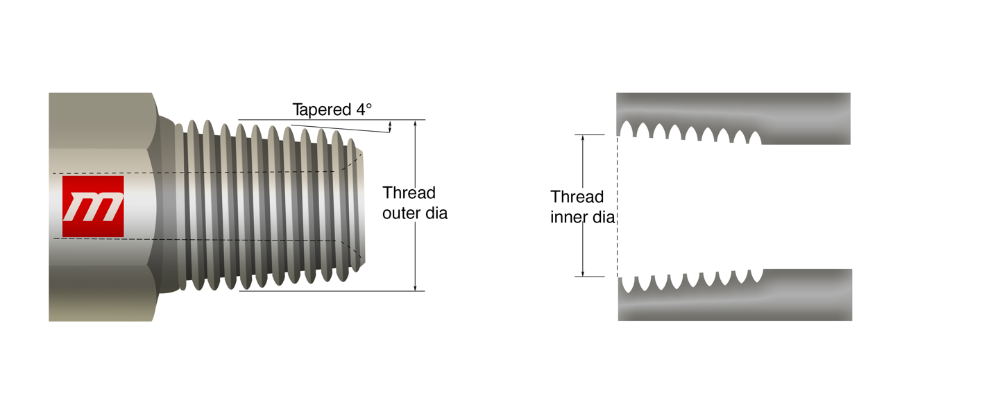
National Pipe Tapered Fuel
National Pipe Taper Fuel (NPTF) is also called Dry seal American National Standard Taper Pipe Thread. It is designed in such a way to give a more leak-free seal without the use of PTFE tape (often referred to by the popular brand name “Teflon”) or another encapsulant material. NPTF strings have a similar fundamental shape yet with peak and root statures adapted to an impedance fit, wiping out the spiral spillage path. In NPTF, the two opposite strings, male and female, connect and the two are mated together and hance a mechanical seal is formed. This makes a dry seal thread with one narrow end of string closely netted with the narrow-threaded hole. If additional sealing is required, Teflon and pipe dope can be applied. This connection for hydraulic applications such as usual hydraulic cylinders, 6-inch bore hydraulic cylinders, 4-inch hydraulic cylinders are not recommended irrespective of the widely accepted use in liquid piping systems. NPTF string attaches are intended to interfere with peak of the mating string, which makes a mechanical seal through string structure disfigured while assembling.
These fittings have “tapered” threads, tapered thread is essential in making mechanical seals and leakproof installation. During installation, the friction created while creating a seal, the metal surfaces may wear up. Therefore, using a lubricant or sealant is crucial to let the moving and rotating parts, work smoothly and efficiently. One example of the beat overall thread sealant used for various applications and fluid systems is gasoila which includes PTFE.
Cooling systems for instance chillers and heat exchangers mostly use these fittings.
Tidbit: NPTF and BSPT both the connectors appear similar but neither one of them can be used as a replacement for the other.

| IS (inch size) | DS(dash size) | TPI (threads per inch) | MT (male thread O.D. in) | FT (female thread O.D. in) | ||
| 1/8 | -2 | 27 | 13/32 | 0.41 | 3/8 | 0.38 |
| 1/4 | -4 | 18 | 17/32 | 0.54 | 1/2 | 0.49 |
| 3/8 | -6 | 18 | 11/16 | 0.68 | 5/8 | 0.63 |
| 1/2 | -8 | 14 | 27/32 | 0.84 | 25/32 | 0.77 |
| 3/4 | -12 | 14 | 1-1/16 | 1.05 | 1 | 0.98 |
| 1 | -16 | 11-1/2 | 1-5/16 | 1.32 | 1-1/4 | 1.24 |
| 1-1/4 | -20 | 11-1/2 | 1-21/32 | 1.66 | 1-19/32 | 1.58 |
| 1-1/2 | -24 | 11-1/2 | 1-29/32 | 1.90 | 1-13/16 | 1.82 |
| 2 | -32 | 11-1/2 | 2-3/8 | 2.38 | 2-5/16 | 2.30 |
National Pipe straight mechanical (NPSM)
A metal seal is created when the male part with 300 internal seat and female part with 300 inverted seats are mated and a connection is made. The connection between them is of mechanical sort as it resists mechanical pullout during the pullout test. These fittings are useful as they consist of a tapered seat which is responsible for reducing leaks on fluid piping systems. Metric compression fittings poses a cutting ring design, this specific property of these fittings is what reduces the vibrations impact on fluid piping and hydraulic systems. These are efficient, reliable, and durable fittings. Moreover, these offer resistant against corrosion as well which makes it even more efficient.
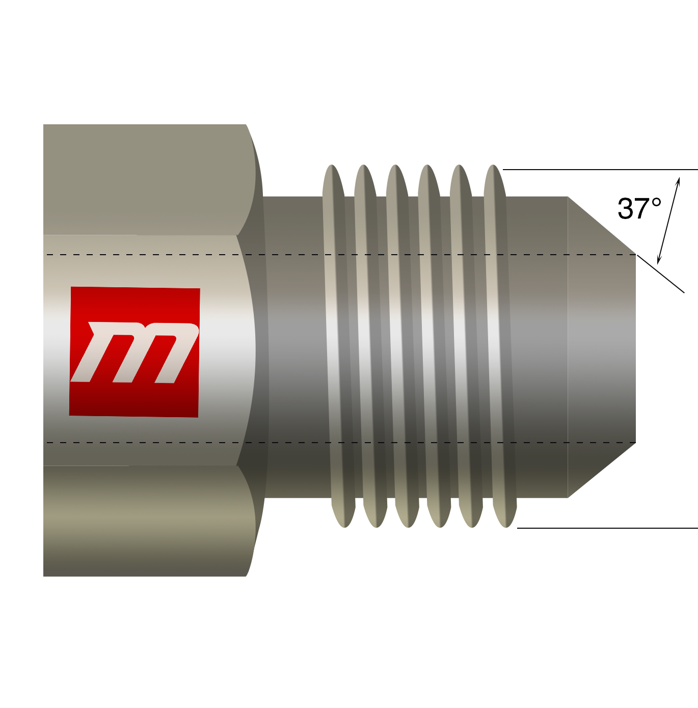
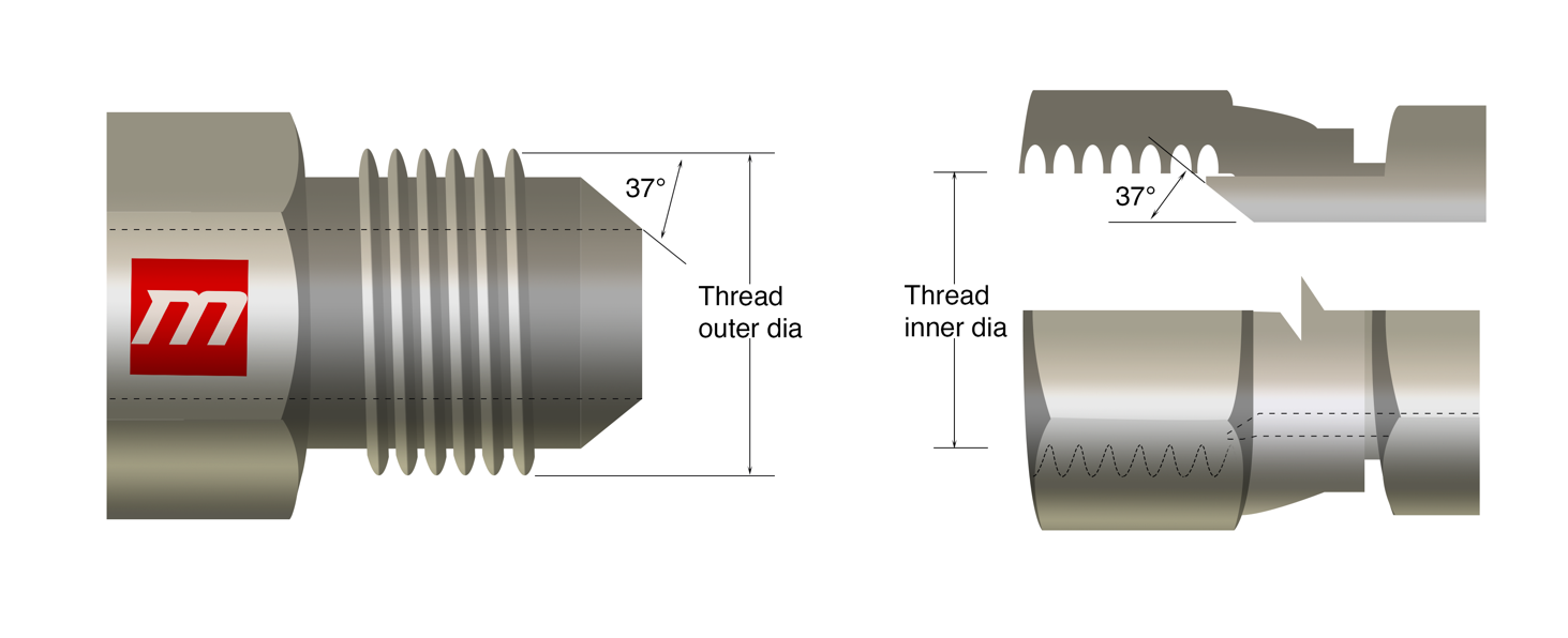
JIC 37° Flare
A flare fitting requires a tube end which is flared; therefore, some altering is done for installation with the help of tools. Uneven and irregular flaring of tubes reduces efficiency and causes invariance as it causes cracks on the pipes and tubes. In order to prevent sealing surface for being irregular and diverging, proper control and supervision should be taken to avoid inconvenient situations. JIC fittings are mostly used where high pressure is involved, particularly in fuel piping or fluid piping. Fitting, flare nut, and sleeves are the components that make tubing system of JIC. Hydraulic applications use these fittings; this connection consists of 37º flare seat along with straight strings for both the opposite male or female of the particular attachment. The flare seats of the male and female seal together During the fusion of the straight strings, both the flare seats of the male and female, are seal together. The straight strings are connected in mechanical manner. Moreover, JIC are generally less expensive. It uses a straight thread according to the unified thread standard.
JIC 37 flare is similar to JIC AN 37 but the latter one is more expensive, almost triple the amount of first one. However, it is quite a task to differentiate between the two visually but can be identified by the way they are written.
| IS (inch size) | DS(dash size) | TS(thread size) | MT (male thread O.D. in) | FT (female thread O.D. in) | ||
| 1/8 | -2 | 5/16 -24 | 5/16 | 0.31 | 9/32 | 0.27 |
| 3/16 | -3 | 3/8 -24 | 3/8 | 0.38 | 11/32 | 0.34 |
| 1/4 | -4 | 7/16 -20 | 7/16 | 0.44 | 13/32 | 0.39 |
| 5/16 | -5 | 1/2 -20 | 1/2 | 0.50 | 15/32 | 0.45 |
| 3/8 | -6 | 9/16 -18 | 9/16 | 0.56 | 17/32 | 0.51 |
| 1/2 | -8 | 3/4 -16 | 3/4 | 0.75 | 11/16 | 0.69 |
| 5/8 | -10 | 7/8 -14 | 7/8 | 0.88 | 13/16 | 0.81 |
| 3/4 | -12 | 1-1/16 -12 | 1-1/16 | 1.06 | 1 | 0.98 |
| 7/8 | -14 | 1-3/16 -12 | 1-3/16 | 1.19 | 1-1/8 | 1.10 |
| 1 | -16 | 1-5/16 -12 | 1-5/16 | 1.31 | 1-1/4 | 1.23 |
| 1-1/4 | -20 | 1-5/8 -12 | 1-5/8 | 1.63 | 1-9/16 | 1.54 |
| 1-1/2 | -24 | 1-7/8 -12 | 1-7/8 | 1.88 | 1-13/16 | 1.79 |
| 2 | -32 | 2-1/2 -12 | 2-1/2 | 2.50 | 2-7/16 | 2.42 |
SAE 45° Flare
This is a flare fitting which uses metal tubing particularly brass tubing for SAE. Low pressure automotive piping applications for example refrigerants with low- pressure including hydro-fluorocarbons, chlorofluorocarbons etc. use these kinds of fittings. . A strong mechanical connection is formed by combining the strings of both joints having a 45° flare seat. long nut in these flare fittings resists vibrations. Its temperature ranges generally from almost -65F to 250F. It works well for high pressure applications. The metal sealing resists pullout during the pullout test when a tiny part of equipment is attached to the fitting and then picked outward upon the suitable stress. This determines that these fittings are strong and suitable for mechanical applications.
Tidbit: Seating angles of SAE J514 do not match SAE 45º regardless of the fact the both these flare threads look identical.
Tidbit: SAE 45° F and JIC 37° Flare connectors seem identical, with an exception of the angle.

| IS (inch size) | DS(dash size) | TS(thread size) | MT (male thread O.D. in) | FT (female thread O.D. in) | ||
| 1/8 | -2 | 5/16 -24 | 5/16 | 0.31 | 9/32 | 0.27 |
| 3/16 | -3 | 3/8 -24 | 3/8 | 0.38 | 11/32 | 0.34 |
| 1/4 | -4 | 7/16 -20 | 7/16 | 0.44 | 13/32 | 0.39 |
| 5/16 | -5 | 1/2 -20 | 1/2 | 0.50 | 15/32 | 0.45 |
| 3/8 | -6 | 5/8 -18 | 5/8 | 0.63 | 9/16 | 0.57 |
| 1/2 | -8 | 3/4 -16 | 3/4 | 0.75 | 11/16 | 0.69 |
| 5/8 | -10 | 7/8 -14 | 7/8 | 0.88 | 13/16 | 0.81 |
| 3/4 | -12 | 1-1/16 -14 | 1-1/16 | 1.06 | 1 | 0.99 |
| 7/8 | -14 | 1-1/4 -12 | 1-1/4 | 1.25 | 1-5/32 | 1.16 |
| 1 | -16 | 1-3/8 -12 | 1-3/8 | 1.38 | 1-9/32 | 1.29 |
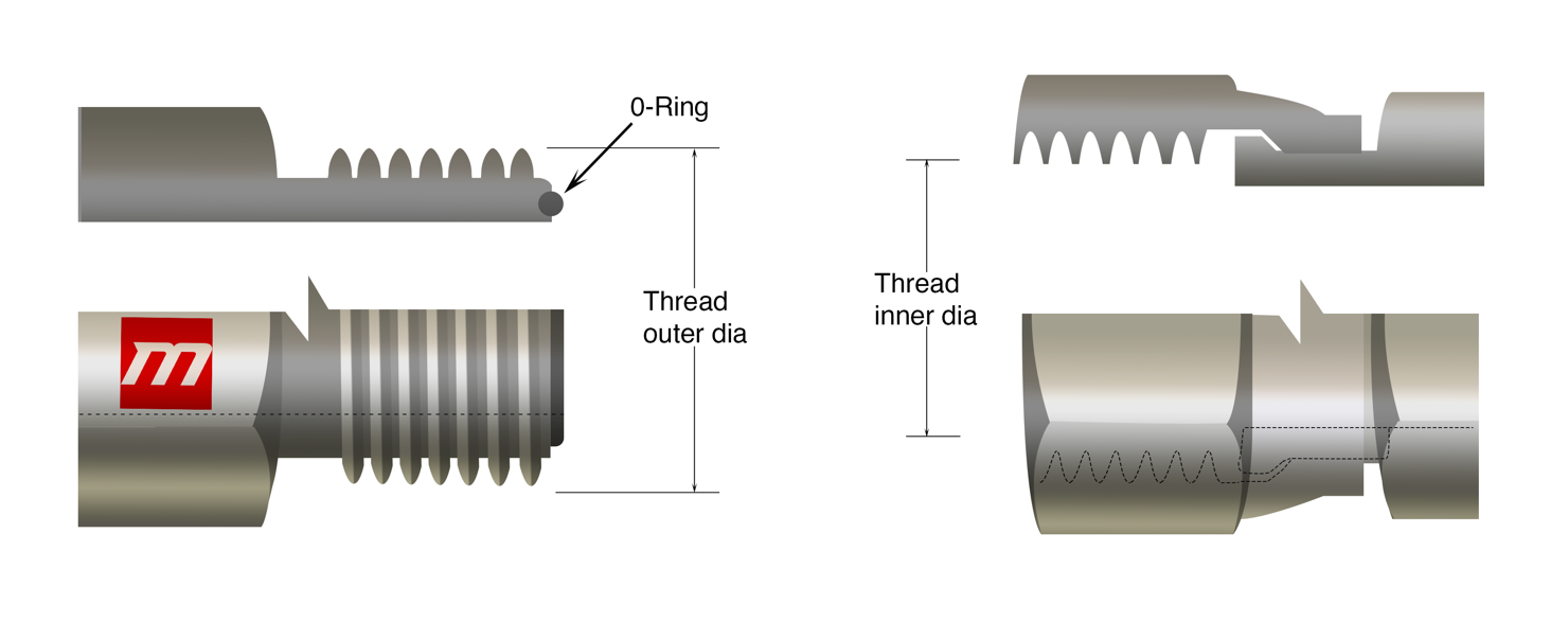
SAE Straight Thread O-ring
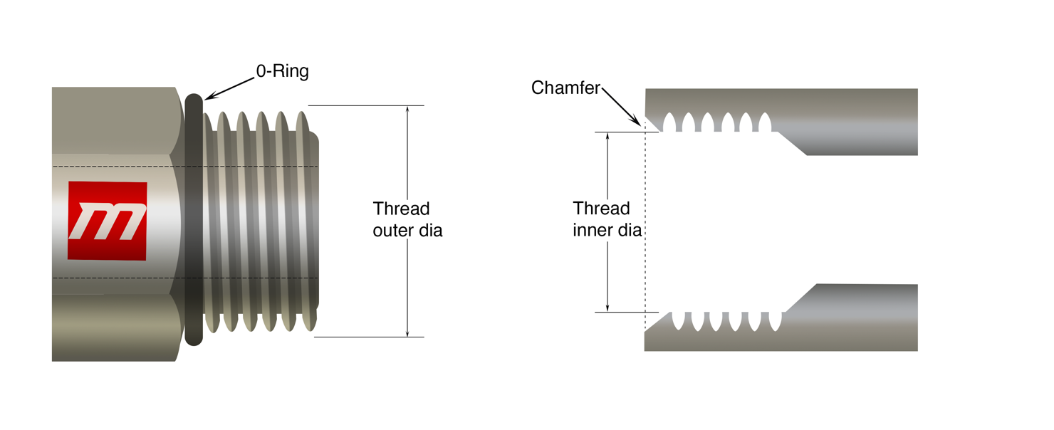
SAE Straight Thread O-ring or O-Ring Boss (ORB) is a multipurpose thread which works well for both medium and high-pressure hydraulic applications. O-Ring Boss has female port which consists of a face seal, straight thread and a chamfer whereas a straight thread and an O-ring makes up the male port. The O-ring is pressed into the chamfer in order to form the seal. Both the opposite male and female threads are attached firmly to build up a connection which is mechanically strong. High pressure hydraulic applications and systems use this connection usually. The male thread contains an O-ring at the base which mates with a chamfer machined into the female counterpoint, which makes this thread type ideal for non-leak applications. Instead of metal seal, SAE provides sealing by the use of O-Rings. These fittings are used to ensure control and retention. Moreover, if we compare these fittings with the NPT, then its evident that SAE are more efficient, easy to access, safe to install and much easier to maintain and reconstruct. Unlike other metal fittings, O-Ring fittings are expensive, hence proper supervision and care must be taken so that these fittings don’t get damaged. Leaks can be prevented be using the correct O-Ring type and not using the one that has been damaged or disfigured.
SAE when compared to compression fittings, also offer advantage because this fitting doesn’t have narrow torque. Narrow torque range is usually responsible for disorientation, leaks and irregularity.

| IS (inch size) | DS(dash size) | TS (thread size) | MT (male thread O.D. in) | FT (female thread O.D. in) | ||
| 1/8 | -2 | 5/16 -24 | 5/16 | 0.31 | 9/32 | 0.27 |
| 3/16 | -3 | 3/8 -24 | 3/8 | 0.38 | 11/32 | 0.34 |
| 1/4 | -4 | 7/16 -20 | 7/16 | 0.44 | 13/32 | 0.39 |
| 5/16 | -5 | 1/2 -20 | 1/2 | 0.50 | 15/32 | 0.45 |
| 3/8 | -6 | 9/16 -18 | 9/16 | 0.56 | 17/32 | 0.51 |
| 1/2 | -8 | 3/4 -16 | 3/4 | 0.75 | 11/16 | 0.69 |
| 5/8 | -10 | 7/8 -14 | 7/8 | 0.88 | 13/16 | 0.81 |
| 3/4 | -12 | 1-1/16 -12 | 1-1/16 | 1.06 | 1 | 0.98 |
| 7/8 | -14 | 1-3/16 -12 | 1-3/16 | 1.19 | 1-1/8 | 1.10 |
| 1 | -16 | 1-5/16 -12 | 1-5/16 | 1.31 | 1-1/4 | 1.23 |
| 1-1/4 | -20 | 1-5/8 -12 | 1-5/8 | 1.63 | 1-9/16 | 1.54 |
| 1-1/2 | -24 | 1-7/8 -12 | 1-7/8 | 1.88 | 1-13/16 | 1.79 |
| 2 | -32 | 2-1/2 -12 | 2-1/2 | 2.50 | 2-7/16 | 2.42 |
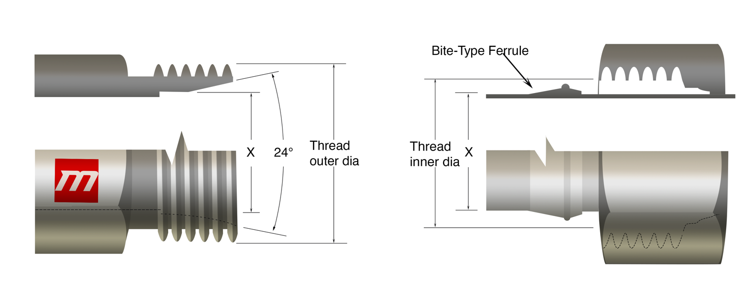
Flareless Compression Fittings
A compression fitting is made up of three main parts. One of the components is a threaded nut, which, when tightened causes the ferrule to compress, this process causes it to conform to the tube’s circumference. Proper orientation of all the parts, more strictly ferrule, is crucial. During the installation of these fittings, no other equipment is used usually. Pressure maintenance from higher to lower and availability of the fitting in variable shapes, sizes and materials makes it the moat efficient one but these fitting lack these two properties. Moreover, for systems and application dealing with vibrations and other dynamic forces, these are not a good choice
Flareless fittings are well known because they are convenient to use and are durable and reliable and are used all over the world. These fittings consist of a connection with a 3-piece design that contains a Nut, Ferrule (Sleeve), and the Body. These are used in places where there is fluctuating pressure and its thus used for higher pressure hydraulic systems. A 240 seat along a straight thread and a compression sleeve also along with a a straight thread for male and female connectors respectively. The 24O seat and the compression sleeve forms the seal for male half whereas for female part a tube, strong female bolt and sleeve mesh together. With the female half, the seal forms between the tubing and compression sleeve. To build a mechanically strong bond both threads are netted jointly.
| IS (inch size) | DS(dash size) | TS (thread size) | MT (male thread O.D. in) | FT (female thread O.D. in) | ||
| 1/8 | -2 | 1/8 -28 | 3/8 | 0.38 | 11/32 | 0.35 |
| 1/4 | -4 | 1/4 -19 | 33/64 | 0.52 | 15/32 | 0.47 |
| 3/8 | -6 | 3/8 -19 | 21/32 | 0.65 | 19/32 | 0.60 |
| 1/2 | -8 | 1/2 -14 | 13/16 | 0.82 | 3/4 | 0.75 |
| 5/8 | -10 | 5/8 -14 | 7/8 | 0.88 | 13/16 | 0.80 |
| 3/4 | -12 | 3/4 -14 | 1-1/32 | 1.04 | 31/32 | 0.97 |
| 1 | -16 | 1 – 11 | 1-5/16 | 1.30 | 1-7/32 | 1.22 |
| 1-1/4 | -20 | 1-1/4 -11 | 1-21/32 | 1.65 | 1-9/16 | 1.56 |
| 1-1/2 | -24 | 1-1/2 -11 | 1-7/8 | 1.88 | 1-25/32 | 1.79 |
| 2 | -32 | 2 -11 | 2-11/32 | 2.35 | 2-1/4 | 2.26 |
| IS (inch size) | DS(dash size) | TPI (threads per inch) | MT (male thread O.D. in) | FT (female thread O.D. in) | ||
| 1/8 | -2 | 27 | 13/32 | 0.41 | 3/8 | 0.38 |
| 1/4 | -4 | 18 | 17/32 | 0.54 | 1/2 | 0.49 |
| 3/8 | -6 | 18 | 11/16 | 0.68 | 5/8 | 0.63 |
| 1/2 | -8 | 14 | 27/32 | 0.84 | 25/32 | 0.77 |
| 3/4 | -12 | 14 | 1-1/16 | 1.05 | 1 | 0.98 |
| 1 | -16 | 11-1/2 | 1-5/16 | 1.32 | 1-1/4 | 1.24 |
| 1-1/4 | -20 | 11-1/2 | 1-21/32 | 1.66 | 1-19/32 | 1.58 |
| 1-1/2 | -24 | 11-1/2 | 1-29/32 | 1.90 | 1-13/16 | 1.82 |
| 2 | -32 | 11-1/2 | 2-3/8 | 2.38 | 2-5/16 | 2.30 |
| IS (inch size) | DS(dash size) | TS(thread size) | MT (male thread O.D. in) | FT (female thread O.D. in) | ||
| 1/8 | -2 | 5/16 -24 | 5/16 | 0.31 | 9/32 | 0.27 |
| 3/16 | -3 | 3/8 -24 | 3/8 | 0.38 | 11/32 | 0.34 |
| 1/4 | -4 | 7/16 -20 | 7/16 | 0.44 | 13/32 | 0.39 |
| 5/16 | -5 | 1/2 -20 | 1/2 | 0.50 | 15/32 | 0.45 |
| 3/8 | -6 | 9/16 -18 | 9/16 | 0.56 | 17/32 | 0.51 |
| 1/2 | -8 | 3/4 -16 | 3/4 | 0.75 | 11/16 | 0.69 |
| 5/8 | -10 | 7/8 -14 | 7/8 | 0.88 | 13/16 | 0.81 |
| 3/4 | -12 | 1-1/16 -12 | 1-1/16 | 1.06 | 1 | 0.98 |
| 7/8 | -14 | 1-3/16 -12 | 1-3/16 | 1.19 | 1-1/8 | 1.10 |
| 1 | -16 | 1-5/16 -12 | 1-5/16 | 1.31 | 1-1/4 | 1.23 |
| 1-1/4 | -20 | 1-5/8 -12 | 1-5/8 | 1.63 | 1-9/16 | 1.54 |
| 1-1/2 | -24 | 1-7/8 -12 | 1-7/8 | 1.88 | 1-13/16 | 1.79 |
| 2 | -32 | 2-1/2 -12 | 2-1/2 | 2.50 | 2-7/16 | 2.42 |
| IS (inch size) | DS(dash size) | TS(thread size) | MT (male thread O.D. in) | FT (female thread O.D. in) | ||
| 1/8 | -2 | 5/16 -24 | 5/16 | 0.31 | 9/32 | 0.27 |
| 3/16 | -3 | 3/8 -24 | 3/8 | 0.38 | 11/32 | 0.34 |
| 1/4 | -4 | 7/16 -20 | 7/16 | 0.44 | 13/32 | 0.39 |
| 5/16 | -5 | 1/2 -20 | 1/2 | 0.50 | 15/32 | 0.45 |
| 3/8 | -6 | 5/8 -18 | 5/8 | 0.63 | 9/16 | 0.57 |
| 1/2 | -8 | 3/4 -16 | 3/4 | 0.75 | 11/16 | 0.69 |
| 5/8 | -10 | 7/8 -14 | 7/8 | 0.88 | 13/16 | 0.81 |
| 3/4 | -12 | 1-1/16 -14 | 1-1/16 | 1.06 | 1 | 0.99 |
| 7/8 | -14 | 1-1/4 -12 | 1-1/4 | 1.25 | 1-5/32 | 1.16 |
| 1 | -16 | 1-3/8 -12 | 1-3/8 | 1.38 | 1-9/32 | 1.29 |
| IS (inch size) | DS(dash size) | TS (thread size) | MT (male thread O.D. in) | FT (female thread O.D. in) | ||
| 1/8 | -2 | 5/16 -24 | 5/16 | 0.31 | 9/32 | 0.27 |
| 3/16 | -3 | 3/8 -24 | 3/8 | 0.38 | 11/32 | 0.34 |
| 1/4 | -4 | 7/16 -20 | 7/16 | 0.44 | 13/32 | 0.39 |
| 5/16 | -5 | 1/2 -20 | 1/2 | 0.50 | 15/32 | 0.45 |
| 3/8 | -6 | 9/16 -18 | 9/16 | 0.56 | 17/32 | 0.51 |
| 1/2 | -8 | 3/4 -16 | 3/4 | 0.75 | 11/16 | 0.69 |
| 5/8 | -10 | 7/8 -14 | 7/8 | 0.88 | 13/16 | 0.81 |
| 3/4 | -12 | 1-1/16 -12 | 1-1/16 | 1.06 | 1 | 0.98 |
| 7/8 | -14 | 1-3/16 -12 | 1-3/16 | 1.19 | 1-1/8 | 1.10 |
| 1 | -16 | 1-5/16 -12 | 1-5/16 | 1.31 | 1-1/4 | 1.23 |
| 1-1/4 | -20 | 1-5/8 -12 | 1-5/8 | 1.63 | 1-9/16 | 1.54 |
| 1-1/2 | -24 | 1-7/8 -12 | 1-7/8 | 1.88 | 1-13/16 | 1.79 |
| 2 | -32 | 2-1/2 -12 | 2-1/2 | 2.50 | 2-7/16 | 2.42 |
O-Ring Face Seal
The O-ring face seal (ORFS) is among the most handy and reliable option for hydraulic connections such as hydraulic cylinders and pumps etc. This connection provides a seal which is authentic and well- founded because of its elasticized seal and thus provides leak- free connection. These seals prevent almost all leaks if it is used properly.This connection can be used for applications with high pressure because it offers great hindrance to leakage. An O-ring with a straight thread connection builds male part whereas a surface held flat with the help of a machine connecting with a straight thread builds the female part. The female half has a machined flat. When. When the O-ring on the male part is pushed onto the flat surface seat on the female part, a seal is made. A nut named swivel is responsible for holding tight the connection. A tailpiece is welded to the tube or hose permanently, and hence the seal is created. An advantage of these fittings is that, they can be disfigured and rearranged any time and this fitting system is also regarded as no clearance fitting system because there is no need to pull strings for fitting seating. Arrangement and dis arrangement can be done by tightening the torque which is recommended or by interchanging the fitting. Another quality of this system is its chock absorbing quality, therefore for application which are exposed to vibrations, O-ring fittings are recommended.
| IS (inch size) | DS(dash size) | TS (thread size) | MT (male thread O.D. in) | FT (female thread O.D. in) | ||
| 1/4 | -4 | 9/16 -18 | 9/16 | 0.56 | 17/32 | 0.51 |
| 3/8 | -6 | 11/16 -16 | 11/16 | 0.69 | 5/8 | 0.63 |
| 1/2 | -8 | 13/16 -16 | 13/16 | 0.82 | 3/4 | 0.75 |
| 5/8 | -10 | 1 -14 | 1 | 1.00 | 15/16 | 0.93 |
| 3/4 | -12 | 1-3/16 -12 | 1-3/16 | 1.19 | 1-1/8 | 1.11 |
| 1 | -16 | 1-7/16 -12 | 1-7/16 | 1.44 | 1-3/4 | 1.36 |
| 1-1/4 | -20 | 1-11/16 -12 | 1-11/16 | 1.69 | 1-5/8 | 1.61 |
| 1-1/2 | -24 | 2 -12 | 2 | 2.00 | 1-15/16 | 1.92 |
SAE Inverted Flare
SAE inverted flare (SAE J512) has its usage in hydraulic brakes, power steering, fuel lines and transmission etc. It has great application in automotive systems, this flare connection has a a 450-seat flared male tubing and a 420-seat connection of male part which is machined. However, there is a sealing surface on the female side due to, what happens to be a 420 seat on the female side. The threads connect together to make a mechanically strong bond.

| IS (inch size) | DS(dash size) | TS (thread size) | MT (male thread O.D. in) | FT (female thread O.D. in) | ||
| 1/8 | -2 | 5/16 -28 | 5/16 | 0.31 | 9/32 | 0.27 |
| 3/16 | -3 | 3/8 -24 | 3/8 | 0.38 | 11/32 | 0.34 |
| 1/4 | -4 | 7/16 -24 | 7/16 | 0.44 | 13/32 | 0.39 |
| 5/16 | -5 | 1/2 -20 | 1/2 | 0.50 | 15/32 | 0.45 |
| 3/8 | -6 | 5/8 -18 | 5/8 | 0.63 | 9/16 | 0.57 |
| 7/16 | -7 | 11/16 -18 | 11/16 | 0.69 | 5/8 | 0.63 |
| 1/2 | -8 | 3/4 -18 | 3/4 | 0.75 | 23/32 | 0.70 |
| 5/8 | -10 | 7/8 -18 | 7/8 | 0.88 | 13/16 | 0.81 |
| 3/4 | -12 | 1-1/16 -16 | 1-1/16 | 1.06 | 1 | 1.00 |
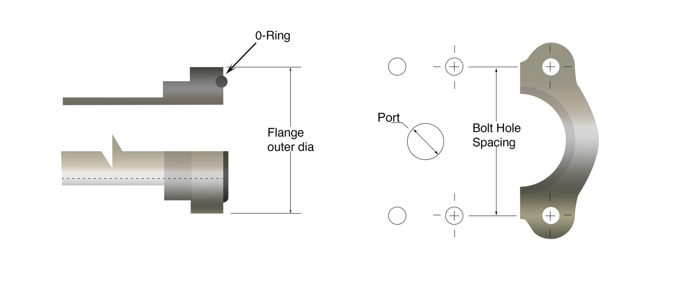
Four-Bolt Flange
The 4-bolt flanged bearing units have direction that can be moved and adjusted to better accommodate long shafts. Four-Bolt Flange can be available for standard inch and metric measurements either with cast iron or thermo-plastic housing etc. Commonly found in fluid power systems, the Four-Bolt Flange shows exceptional performance when it is connected to a 1/2″ to 3″ hose or canal.
The O-ring and the smooth face build a seal via male and female parts respectively. A seal is created between O-ring and the female port while the O-ring seats on the ring groove of the male part. Two clamp halves, held by four bolts, The connection is held strongly with the help of bolts and clamp halves, both four and two respectively.
These are available in two pressure groups:
- Standard pressure
- High pressure
| IS (inch size) | DS(dash size) | Bolt Spacing | Flange O.D. | Bolt Spacing | Flange O.D. |
| 1/2 | -8 | 1-1/2 | 1-3/16 | 1-19/32 | 1-1/4 |
| 3/4 | -12 | 1-7/8 | 1-1/2 | 2 | 1-5/8 |
| 1 | -16 | 2-1/16 | 1-3/4 | 2-1/4 | 1-7/8 |
| 1-1/4 | -20 | 2-5/16 | 2 | 2-5/8 | 2-1/8 |
| 1-1/2 | -24 | 2-3/4 | 2-3/8 | 3-1/8 | 2-1/2 |
| 2 | -32 | 3-1/16 | 2-13/32 | 3-13/16 | 3-1/8 |
| 2-1/2 | -40 | 3-1/2 | 3-5/16 | n/a | n/a |
| 3 | -48 | 4-3/16 | 4 | n/a | n/a |
O-Ring Pilot Threads
O-Ring Pilot Threads are handy and convenient and have various types of sizes, shapes, combinations and materials. The ORB fittings are made in such a way that they resist complications associated with over-assembly. It is easily maintainable and re-usable as well. O-Rong pilot threads come in both adjustable and non-adjustable model. ORB fittings have vast applications in numerous fields including air conditioning services both automotive and commercial. There is a pilot in both the opposite male female parts of various range. The O-ring is made to compress to make a seal. A strong mechanical bond is formed when threads are joined tightly.

| IS | DS | MT | FT | ||
| TS | Thread O.D. | TS | Thread I.D. | ||
| 3/8 | -6 | 5/8 -18 | 5/8 | 5/8 -18 | 9/16 |
| 1/2 | -8 | 3/4 -18 | 3/4 | 3/4 -16 | 11/16 |
| 5/8 | -10 | 7/8 -18 | 7/8 | 7/8 -14 | 13/16 |
| 3/4 | -12 | 1-1/16 -16 | 1-1/16 | 1-1/16 -14 | 1 |
| IS | DS | Long pilot | Short pilot | ||
| Bead O.D.(in) | Pilot Length (in) | Bead O.D.(in) | Pilot Length (in) | ||
| 3/8 | -6 | 0.52 | 0.28 | 0.52 | 0.19 |
| 1/2 | -8 | 0.64 | 0.39 | 0.64 | 0.19 |
| 5/8 | -10 | 0.77 | 0.39 | 0.77 | 0.19 |
| 3/4 | -12 | 0.91 | 0.39 | 0.91 | 0.19 |
Worldwide Connections
Fluid ports and connectors are a necessity all over the world as they are used in several applications. From expensive tools to cheap and affordable ones used for fluid piping systems, short hydraulic cylinders and cascade hydraulic cylinders etc. Therefore, some of the fittings manufactured and exported internationally are listed and briefly explained as follows;
British Standard Pipe
- British connections are available in two categories;
- British Standard Pipe Parallel (BSPP)
- British Standard Pipe Tapered (BSPT)
British Standard Pipe
It is an internationally adopted set of standards in which fitting and pipes are joined and sealed and threads are matted, by mating an external thread with an internal thread. Except For North America, it is one one the most widely used standard procedures in plumbing and fluid-piping systems. It is used for plumbing as it is low-pressured but not recommended for hydraulic systems of medium and high-pressure range.
British Standard Pipe Parallel
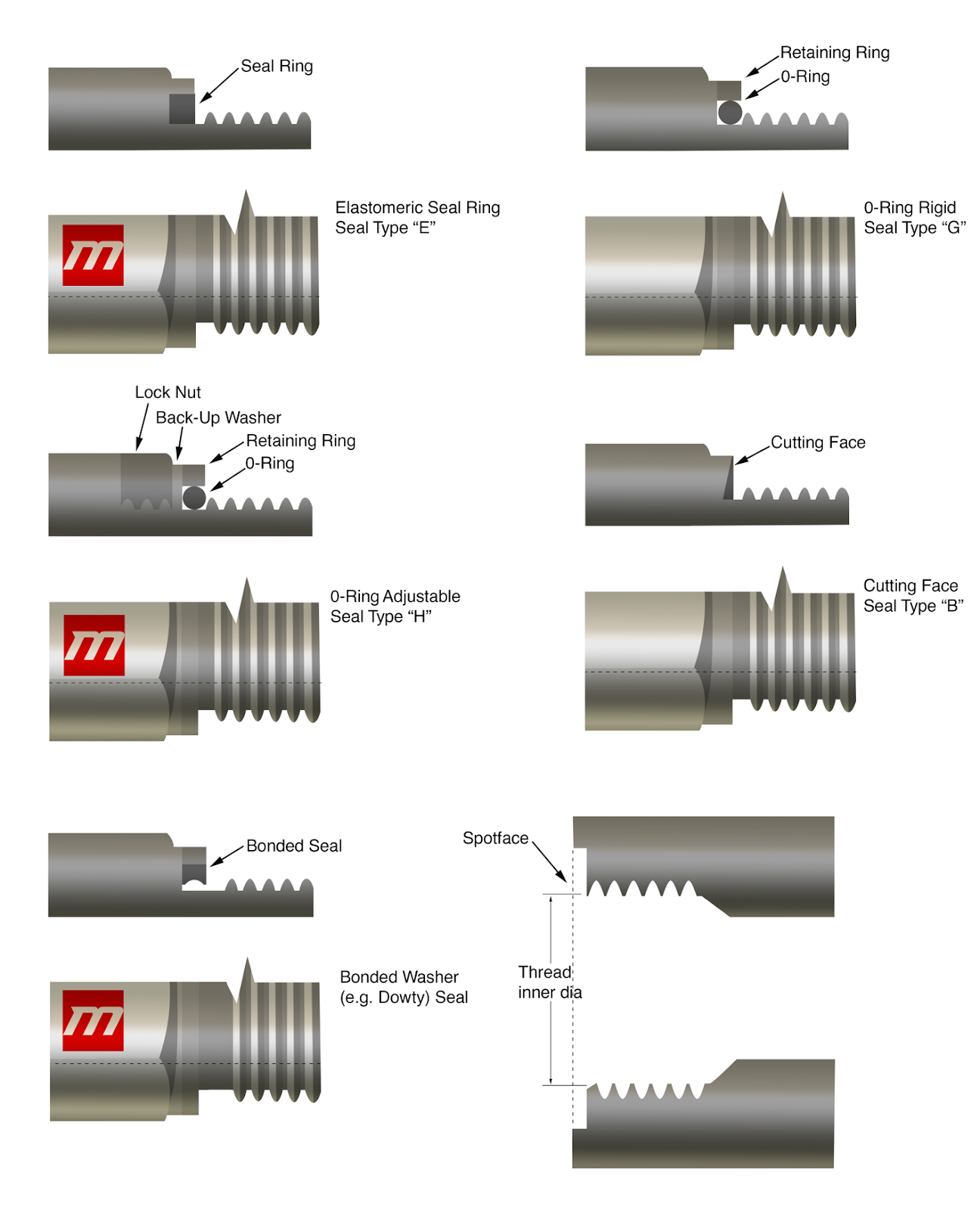
A seal is made with narrow nose of the swivel from female side and a 300-seat male end. For sealing process, an affix seal ring is used in BSPP. The ring seal is interposed in the middle of a shoulder and the front of the male and female fitting respectively and is pressed set up. BSPP pressure checks have a more extended male string and utilize a copper squash washer that is crushed in the middle of the lower part of the external fitting and the lower part of the internal. BSPP opening framing a pressing factor tight seal. No string sealant is expected to frame a seal.
Tidbit:
The male end of it is similar to NPSM male, however they have different pitches of threads and thus cannot be replaced.
| IS (inch size) | DS(dash size) | TS (thread size) | MT (male thread O.D. in) | FT (female thread O.D. in) | ||
| 1/8 | -2 | 1/8 -28 | 3/8 | 0.38 | 11/32 | 0.35 |
| 1/4 | -4 | 1/4 -19 | 33/64 | 0.52 | 15/32 | 0.47 |
| 3/8 | -6 | 3/8 -19 | 21/32 | 0.65 | 19/32 | 0.60 |
| 1/2 | -8 | 1/2 -14 | 13/16 | 0.82 | 3/4 | 0.75 |
| 5/8 | -10 | 5/8 -14 | 7/8 | 0.88 | 13/16 | 0.80 |
| 3/4 | -12 | 3/4 -14 | 1-1/32 | 1.04 | 31/32 | 0.97 |
| 1 | -16 | 1 – 11 | 1-5/16 | 1.30 | 1-7/32 | 1.22 |
| 1-1/4 | -20 | 1-1/4 -11 | 1-21/32 | 1.65 | 1-9/16 | 1.56 |
| 1-1/2 | -24 | 1-1/2 -11 | 1-7/8 | 1.88 | 1-25/32 | 1.79 |
| 2 | -32 | 2 -11 | 2-11/32 | 2.35 | 2-1/4 | 2.26 |
British Standard Pipe Tapered
The seal is formed in the threads when the narrow external fitting connects with a narrow internal fitting.
In this fitting system, it is advisable to use both male and female threads properly tapered. This helps in preventing the spiral leakage.
Tidbit:
Although the size and thread form of BSPT male end is similar to the NPTF, however, it is not feasible for these to reciprocate.
| IS (inch size) | DS(dash size) | TS (thread size) | MT (male thread O.D. in) | FT (female thread O.D. in) | ||
| 1/8 | -2 | 1/8 -28 | 3/8 | 0.38 | 11/32 | 0.35 |
| 1/4 | -4 | 1/4 -19 | 33/64 | 0.52 | 15/32 | 0.47 |
| 3/8 | -6 | 3/8 -19 | 21/32 | 0.65 | 19/32 | 0.60 |
| 1/2 | -8 | 1/2 -14 | 13/16 | 0.82 | 3/4 | 0.75 |
| 5/8 | -10 | 5/8 -14 | 7/8 | 0.88 | 13/16 | 0.80 |
| 3/4 | -12 | 3/4 -14 | 1-1/32 | 1.04 | 31/32 | 0.97 |
| 1 | -16 | 1 – 11 | 1-5/16 | 1.30 | 1-7/32 | 1.22 |
| 1-1/4 | -20 | 1-1/4 -11 | 1-21/32 | 1.65 | 1-9/16 | 1.56 |
| 1-1/2 | -24 | 1-1/2 -11 | 1-7/8 | 1.88 | 1-25/32 | 1.79 |
| 2 | -32 | 2 -11 | 2-11/32 | 2.35 | 2-1/4 | 2.26 |
British Standard Pipe Parallel Threads with Flat Face Port
The parallel threads in this connection adapt to several rings or washers in order to make a seal. The interior end comprising of a smooth flat surface and the exterior end join to form a seal.
| IS (inch size) | DS(dash size) | TS (thread size) | MT (male thread O.D. in) | FT (female thread O.D. in) | ||
| 1/8 | -2 | 1/8 -28 | 3/8 | 0.38 | 11/32 | 0.35 |
| 1/4 | -4 | 1/4 -19 | 33/64 | 0.52 | 15/32 | 0.47 |
| 3/8 | -6 | 3/8 -19 | 21/32 | 0.65 | 19/32 | 0.60 |
| 1/2 | -8 | 1/2 -14 | 13/16 | 0.82 | 3/4 | 0.75 |
| 5/8 | -10 | 5/8 -14 | 7/8 | 0.88 | 13/16 | 0.80 |
| 3/4 | -12 | 3/4 -14 | 1-1/32 | 1.04 | 31/32 | 0.97 |
| 1 | -16 | 1 – 11 | 1-5/16 | 1.30 | 1-7/32 | 1.22 |
| 1-1/4 | -20 | 1-1/4 -11 | 1-21/32 | 1.65 | 1-9/16 | 1.56 |
| 1-1/2 | -24 | 1-1/2 -11 | 1-7/8 | 1.88 | 1-25/32 | 1.79 |
| 2 | -32 | 2 -11 | 2-11/32 | 2.35 | 2-1/4 | 2.26 |
Metric Threads with Flat Face Port
The parallel threads in this connection adapt to several rings or washers in order to make a seal. The interior end comprising of a smooth flat surface and the exterior end join to form a seal.
| MTS | MT | FT |
| M8 x 1.0 | 8 | 7 |
| M10 x 1.0 | 10 | 9 |
| M12 x 1.5 | 12 | 10.5 |
| M14 x 1.5 | 14 | 12.5 |
| M16 x 1.5 | 16 | 14.5 |
| M18 x 1.5 | 18 | 16.5 |
| M20 x 1.5 | 20 | 18.5 |
| M22 x 1.5 | 22 | 20.5 |
| M24 x 1.5 | 24 | 22.5 |
| M26 x 1.5 | 26 | 24.5 |
| M27 x 2.0 | 27 | 25 |
| M33 x 2.0 | 33 | 31 |
| M36 x 2.0 | 36 | 34 |
| M42 x 2.0 | 42 | 40 |
| M45 x 2.0 | 45 | 43 |
| M48 x 2.0 | 48 | 46 |
Metric Port and Stud Ends
It consists of O-ring from male end and, a chamfer and a machined surface from female end, with a straight thread including in both. A seal is made when the male end O-Ring squeezes the female end on the chamfer.
The straight threads mesh to form A solid secure bond is formed, when straight threads are netted jointly. The nature of the bond is mechanical.
| MTS | MT | FT (mm) |
| M8 x 1.0 | 8 | 7 |
| M10 x 1.0 | 10 | 9 |
| M12 x 1.5 | 12 | 10.5 |
| M14 x 1.5 | 14 | 12.5 |
| M16 x 1.5 | 16 | 14.5 |
| M18 x 1.5 | 18 | 16.5 |
| M22 x 1.5 | 22 | 20.5 |
| M27 x 2.0 | 27 | 25 |
| M33 x 2.0 | 33 | 31 |
| M42 x 2.0 | 42 | 40 |
| M48 x 2.0 | 48 | 46 |
| M60 x 2.0 | 60 | 58 |
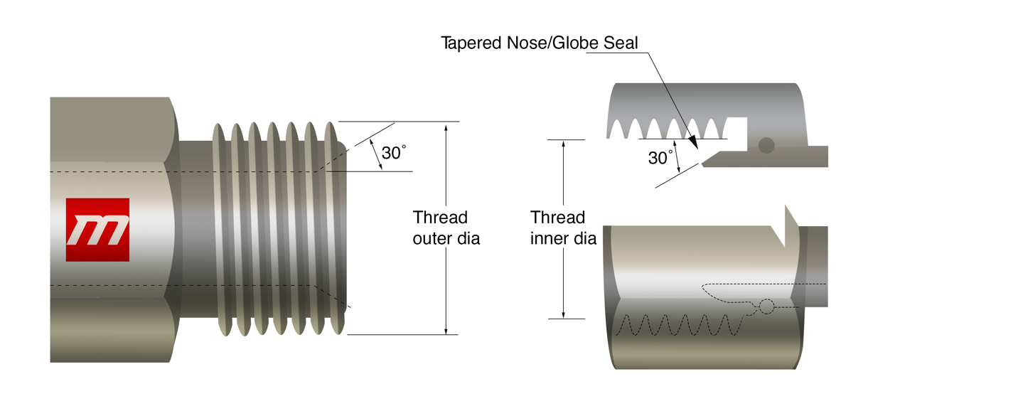
Metric 60° Cone
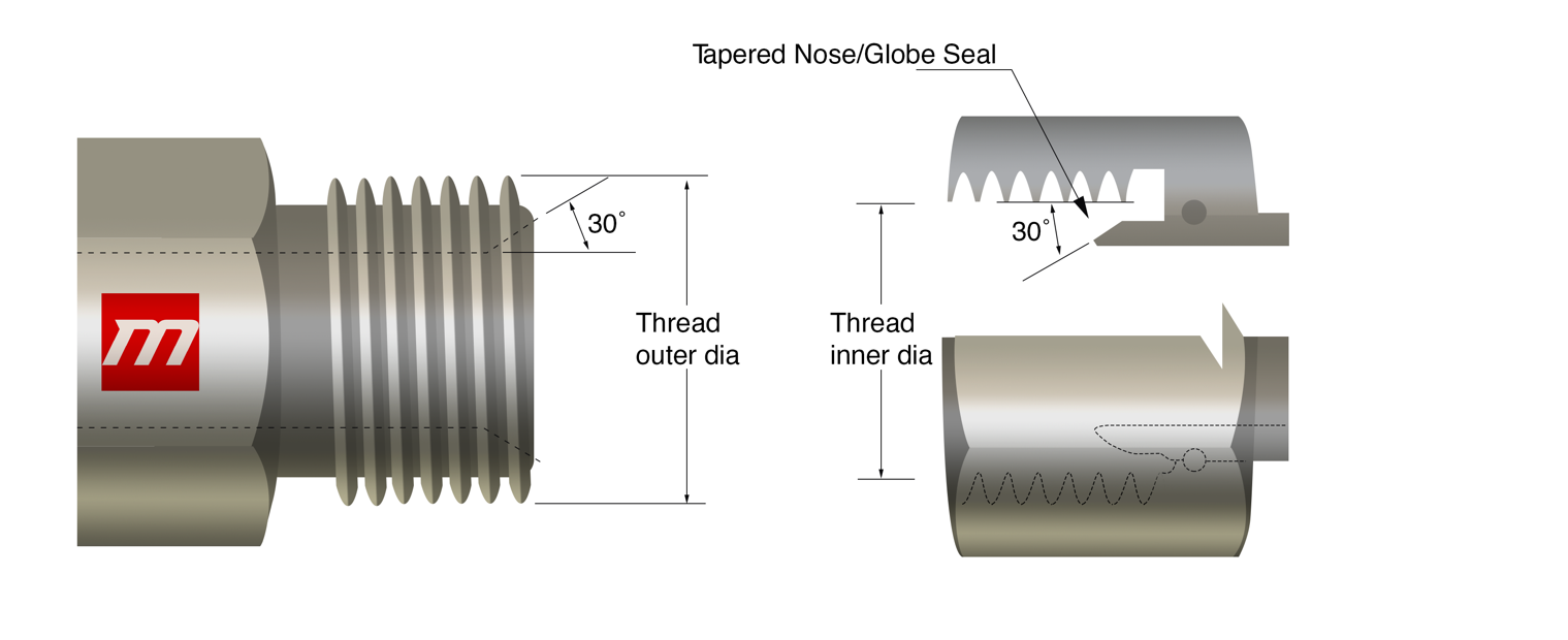
The male connector has a 60° recessed cone and a straight thread; the female has a straight thread as well, and a globe seal seat.
The recessed cone and tapered nose of the male and female end together form the seal.
Both ends let their threads net together for forming a strong mechanical bond. In hydraulic systems such type of connections is usual.
| Pipe (mm) | MTS | MT (mm) | FT (mm) |
| 6 | M12 x 1.5 | 12 | 10.5 |
| 8 | M14 x 1.5 | 14 | 12.5 |
| 10 | M16 x 1.5 | 16 | 14.5 |
| 12 | M18 x 1.5 | 18 | 16.5 |
| 15 | M22 x 1.5 | 22 | 20.5 |
| 18 | M26 x 1.5 | 26 | 24.5 |
| 22 | M30 x 1.5 | 30 | 28.5 |
| 28 | M38 x 1.5 | 38 | 36.5 |
| 35 | M45 x 1.5 | 45 | 43.5 |
| 52 | M52 x 1.5 | 52 | 50.5 |
Japanese Industrial Standard Flare
These fittings have flare ends. The tube end should not end up being uneven or irregular during flaring the end of tube, it renders the performs inefficient. Japanese standard fittings are available in large variety of dimensions. Fir installation purposes, proper calculation of threads should be done to ensure leak resistant connection. It consists of a 30 and a 300 seat both with a straight thread of male and female end respectively.
vThe 37° Flare connection resembles this connection but it has 30 seat dimensions and proportions similar to that of BSPP, that is the reason which distinguishes between this connection and the American 37° Flare.
| IS (inch size) | DS(dash size) | TS (thread size) | MT (male thread O.D. in) | FT (female thread O.D. in) | ||
| 1/8 | -2 | 1/8 -28 | 3/8 | 0.38 | 11/32 | 0.35 |
| 1/4 | -4 | 1/4 -19 | 33/64 | 0.52 | 15/32 | 0.47 |
| 3/8 | -6 | 3/8 -19 | 21/32 | 0.65 | 19/32 | 0.60 |
| 1/2 | -8 | 1/2 -14 | 13/16 | 0.82 | 3/4 | 0.75 |
| 5/8 | -10 | 5/8 -14 | 7/8 | 0.88 | 13/16 | 0.80 |
| 3/4 | -12 | 3/4 -14 | 1-1/32 | 1.04 | 31/32 | 0.97 |
| 1 | -16 | 1 – 11 | 1-5/16 | 1.30 | 1-7/32 | 1.22 |
| 1-1/4 | -20 | 1-1/4 -11 | 1-21/32 | 1.65 | 1-9/16 | 1.56 |
| 1-1/2 | -24 | 1-1/2 -11 | 1-7/8 | 1.88 | 1-25/32 | 1.79 |
| 2 | -32 | 2 -11 | 2-11/32 | 2.35 | 2-1/4 | 2.26 |
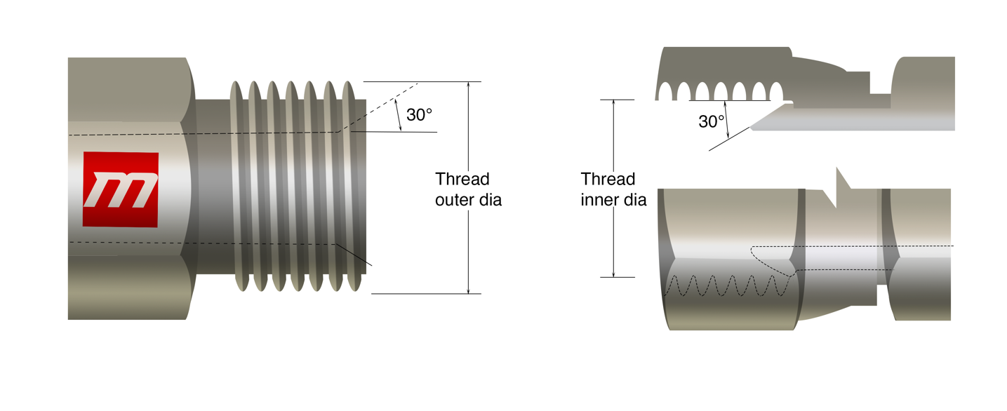
Komatsu 30° Flare
The measurement of Komatsu connection starts with estimating the outside diameter of male threads and inside diameter of female threads, after this the number of strings per inch or more precisely pitch of string is calculated using screw gauge also known as thread pitch gauge. The flare angle which is 30 should be checked and values must be compare with the chart to attain accurate measurement. It is a 30° seat parallel metric thread connection which is common on Komatsu equipment.
There exists a similarity between the JIS metric connection and the JIS 300 flare, the concluding one has thread dimensions similar to BSPP.
| DS | MTS | MT (mm) | FT (mm) |
| -6 | M18 x 1.5 | 18 | 16.5 |
| -8 | M22 x 1.5 | 22 | 20.5 |
| -10 | M24 x 1.5 | 24 | 22.5 |
| -12 | M30 x 1.5 | 30 | 28.5 |
| -16 | M33 x 1.5 | 33 | 31.5 |
| -20 | M36 x 1.5 | 36 | 34.5 |
| -24 | M42 x 1.5 | 42 | 40.5 |